12/22/2001
Now that the bottom of the craft is skinned and sealed, the next step
is the construction of the lift duct. I am deviating from the plans
on the lift duct. The plans call for a lift duct which is basically
a cylinder made from 1/8" plywood. An optional inlet ring can be installed
to improve the lift performance. The inlet ring keeps the lift air
flowing smoothly. The 2 things that I don't like about this approach
are the looks inlet ring and the thin duct wall. My lift duct will
have the same 1/8" plywood cylinder wall, but will be wrapped with 2"
of foam and a layer of fiberglass. The foam wrap will not only add
strength, but will allow the top 2" of the duct to be rounded which
will eliminate the need for the inlet ring. This will also make the
front of the craft look cleaner.
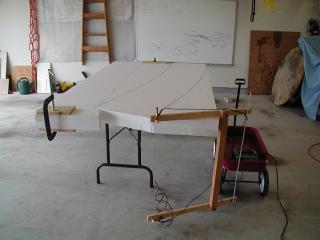
The pictures on right show:
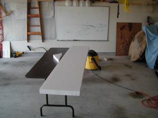
- Foam layout for the thrust and lift duct.
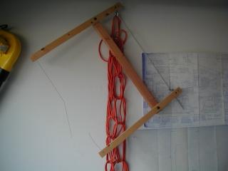
- Jig for drawing the arc for the trust duct.
- Hotwire cutting the foam.
- The broken hotwire. Had to finish with a saw. :(
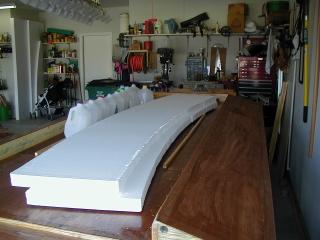
- The thrust duct foam to be used later.
- The lift duct foam ready for fiberglass.
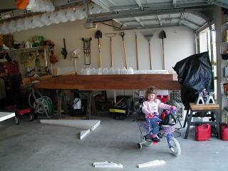
- Hovercraft construction helper.
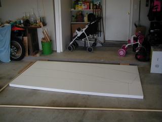
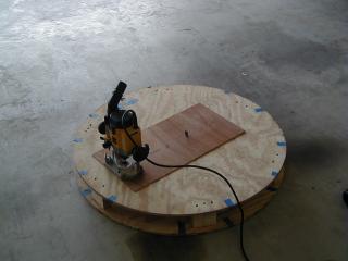
- Cutting the form for the lift duct from the previous hovercaft form.
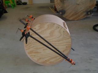
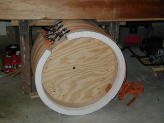
- Lift duct plywood cylinder wrapped around the form.
12/26/2001
Here is my first mistake. When I calculated the length for the foam
that will be used to wrap tha lift duct, I came up a little short. The
outside diamter of the duct is 26 1/2 inches. A 26 1/2 inch diameter
needs 83 1/4 inches of foam to wrap the duct. Or so I thought. Since
the foam wraps around the duct, the overall diameter of the duct will
be 30 1/2 inches. This means that 95 inches of foam is needed to wrap
the duct. I have the other 12 inches ready to be epoxied to the duct.
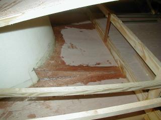
While I was waiting for the epoxy to cure on the lift duct, I cut a hole in the bottom of the craft for the lift duct. It was strange cutting a hole in the bottom. Hope that I measured correctly!
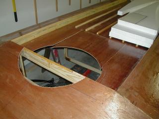
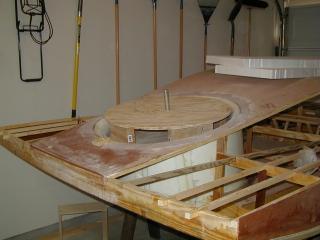
12/28/2001
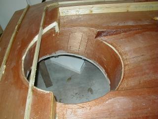
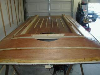
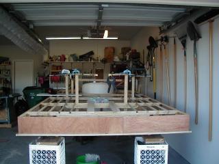
The bottom side of the craft is finished for now and the missing piece
of foam in the lift duct is set in place. The lift engine even fits
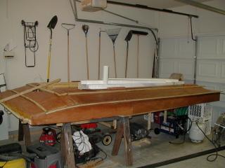
nicely in the lift duct. This means that it is time to flip the craft
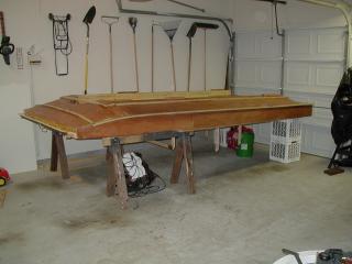
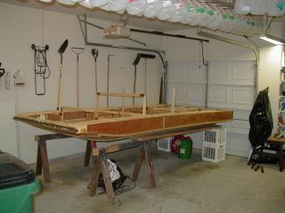
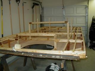
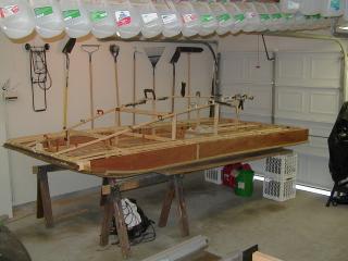
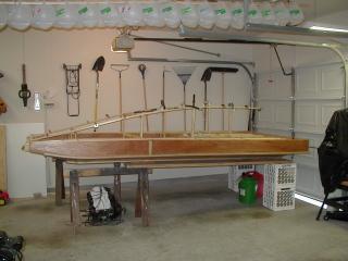
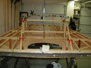
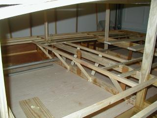
over and start working on the top side. There were a few stringers that
had not been installed. The top cockpit stringers have a sharp bend
toward the rear of the craft. The first attempt at the bend resulted
in both of the stringer breaking. Since each stringer is 3/4 inch
square, I ripped down some 3/8 x 3/4 lumber. By using two 3/8 inch
sections epoxied together, the curve was achieved without breaking.
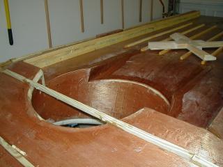
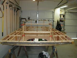
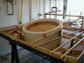
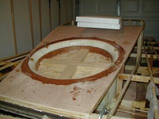
After the stringers were set in place, it was time to set the lift duct. The first item of business is to mark and cut a section from the top of rib R2. After the top of R2 is removed, the duct is set down onto the hull and fitted. The duct needs to be fiberglassed to the hull. This is different than the plans, but it is turning out nicely. With just being glued to the hull, it is quite solid. Once it is completely glassed, it should be bullet proof. :)

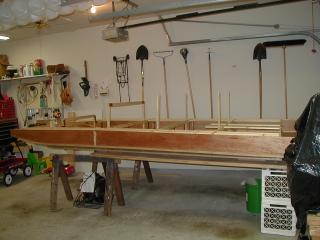
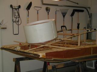
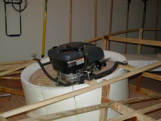
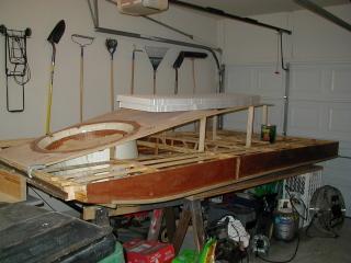
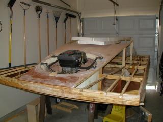
12/30/2001
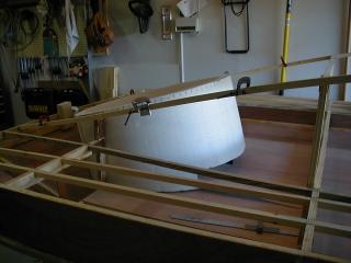
It finally got too cold to use the epoxy. In spite of the sub 50
degree temperatures, I braved the elements and shaped the inlet of the
lift duct. This was done with sand paper and a little elbow grease.
The foam sands very easily. It had to be easy if I was not using a
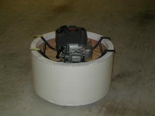
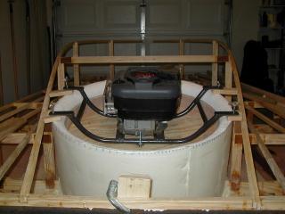
power tool. After the duct was shaped, the lift engine was set in
place for a test fit. The lift engine stand was made by a friend
and I wanted to see how it would fit. It fits perfectly.
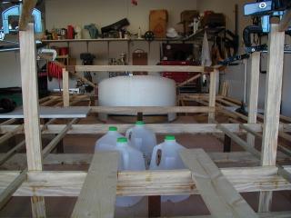
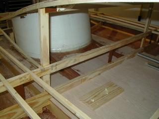
1/20/2002
Construction has slowed down since the first of the year. I haven't
had time to perform any major tasks, just little ones whenever time
allows. The top of the lift duct is glassed in place with the lift
engine mounts. The lower portion of the lift duct has been glassed
inside of the cockpit. The frame for the seat is in place, and the
extra 1/4" on the cockpit floor has been added. The floor of the
cockpit is very steady. The EMT is in place for the torque tube
steering. I wanted to have the steering tube in place so that I
could tell where to place the positive floatation.
2/2/2002
The time has finally come to remove the form from the lift duct. The
construction manual says to "kick the form out." Sounds simple enough.
I had to use a lot of nails when attaching the plywood to the form.
All of the nails made the removal of the duct difficult. It took about
a half hour of some serious whacking with small sledge hammer to get the
form out. But I did find out that the duct is very solid.
2/10/2002
Hopefully this will be the last time the craft is bottom side up.
Finished fiberglassing the bottom of the lift duct. Still have to add
the splitter. That will be added after the lift fan is finished.