1/27/2002
Started building the thrust duct. This is a lot bigger than the thrust
duct on my previous craft, the UH-10F. That craft had a 36" duct.
This craft is getting a 54" duct. The extra 18" does not seem like a
lot, but the 54" disks used to form the duct are big! This should
move plenty of air. :)
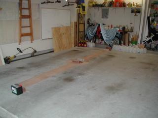
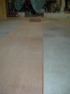
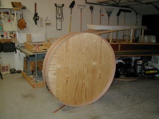
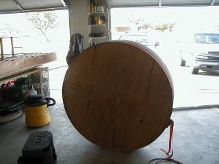
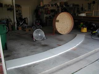
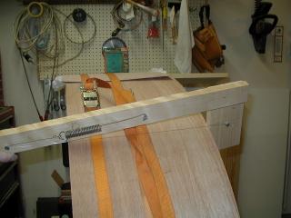
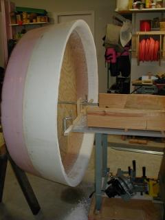
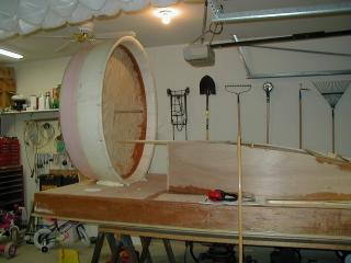
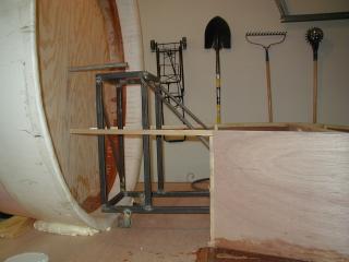
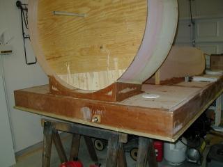
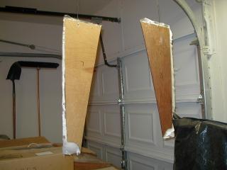
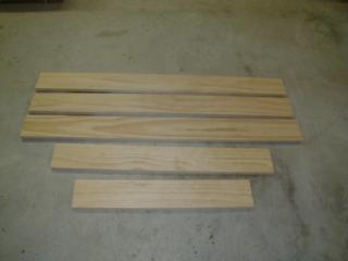
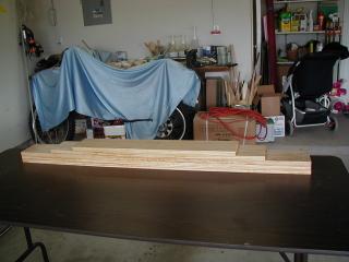
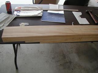
The pictures on right show:
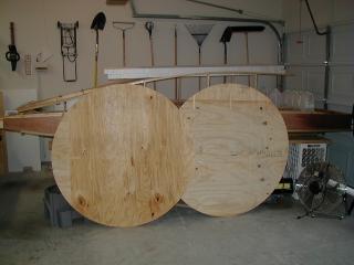
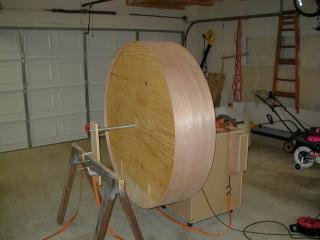
- The 2 54" disks usde to form the duct. These were cut using a router and a circle jig. The cirgle jig was a piece of scrap 1/8" plywood bolted to the base of the router and long enough to cover the radius of the disk.
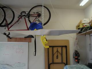
- The plywood that will form the inside cylinder of the duct. This was made from 2 pieces fiberglassed together to make 1 very long piece.
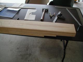
- This is a close-up of the thrust duct plywood. I ran a string to make sure that the 2 pieces of plywood are joined correctly. If they are not joined correctly, the duct will be out of round.
2/2/2002
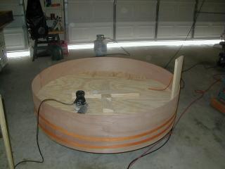
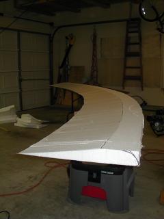
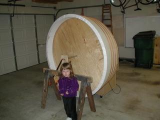
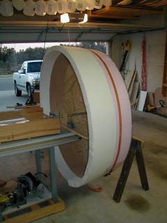
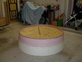
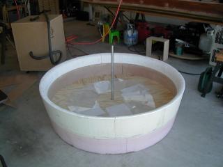
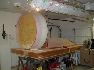
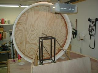
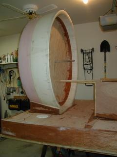
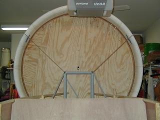
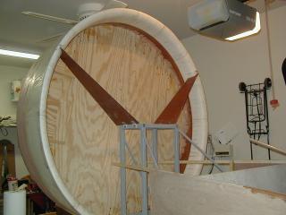
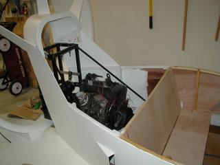
The plywood has been wrapped around the giant 54" discs which make up
the form for the thrust duct. This thing is big! While I was working
on the lift duct, I had set the lift fan in the thrust duct. You can
hardly tell that the fan is in the duct. The thrust duct foam has been
joined together and one side has been fiberglassed. The other side of
the foam will have an angle cut out with the hot wire. This will give
the taper on the outside of the duct.
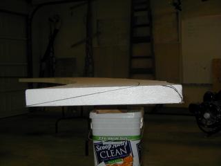
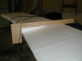
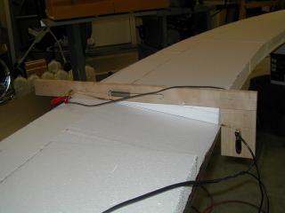
2/4/2002
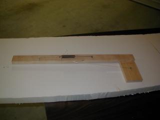
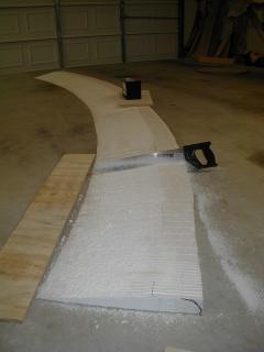
Time to cut the taper into the thrust duct foam. I made a hotwire jig
just for cutting the angle into the foam. It cuts a slice out of the
foam which is the same length of the thrust duct plywood. The cut side
of the foam will be wrapped against the plywood.
2/10/2002, 2/16/2002, 2/17/2002
Cut the slots in the foam in order to bend the foam around the plywood
cylinder. Everything was looking good. I did a quick test fit. It
wasn't perfect, but it looked like it should work. Wrong. The trailing
edge of the duct had a small gap. I thought that the gap would be
closed when the straps pulled the foam tight. That did not happen.
Instead, the foam wrinkled around the trailing edge. I found out where
I went wrong. The numbers used to cut the foam arc were based on cutting
an 18" angle in the foam. Since I cut a 13" angle, I should have created
a little bit different arc.
I was able to save the duct by removing the trailing 8" of foam and laying new foam and fiberglass. Lesson learned: always double check your numbers, never assume anything.
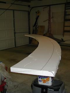
2/19/2002
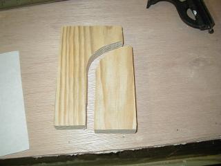
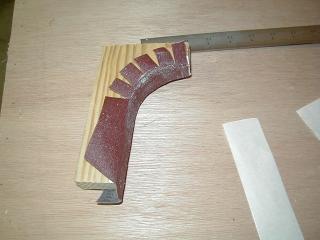
Time to round off the leading edge of the thrust duct. I made a
template of the desired curve from a block of wood. The inside curve
of the template was lined with sandpaper using double sided tape. A
little bit of elbow grease, and the leading edge began to take shape.
Sanding the foam goes quickly even without power tools. The duct is
now ready for fiberglass on the leading edge.
2/23/2002
Fiberglassed the leading edge of the duct. It is ready to be mounted
on the hull as soon as the skinning is completed.
3/3/2002
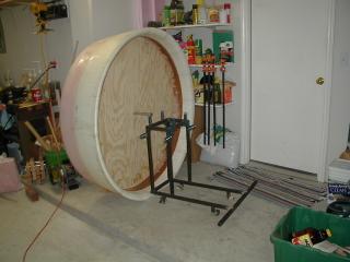
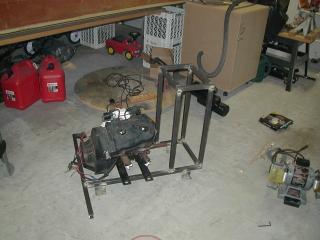
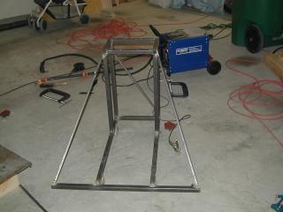
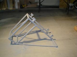
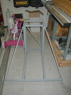
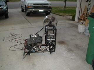
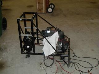
I was able to get 2 major items done this weekend. First, the engine
stand is fully assembled. All it needs is some paint. Second, the
thrust duct has been attached to the craft. It still needs the supports,
but at least it is on the craft. Now I can finish skinning the rest of
craft and making the engine cover.
3/9/2002
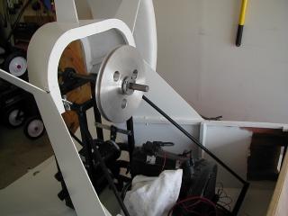
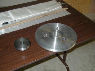
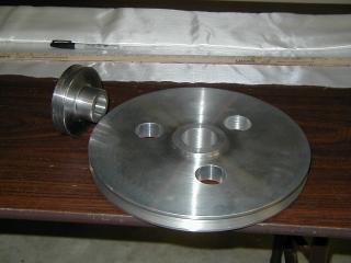
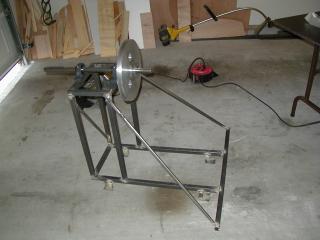
Both of my custom made pulleys arrived. Thanks Dad! The big pulley is
made from aluminum and the small one is steel. I just had to set the
prop shaft on the engine stand with the pulley. That pulley is the best
looking item on the whole craft. Probably because I didn't make it. :)
The bottom of the thrust duct is now fiberglassed to the hull. It is not going anywhere. Also was able to put the first coat of primer on the engine stand.
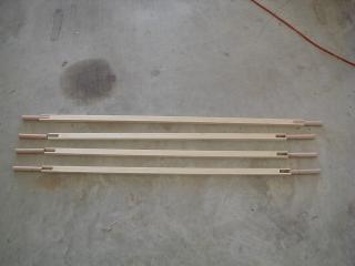
I started making the center of the rudders. The plans say to round off the ends of a 3/4" x 1" shaft. That might work well with a lathe, but I don't have a lathe. I did see somewhere on the net that a builder notched out the rudder shafts and inserted hardwood rods. I used my tenoning jig to cut the notches and create a flat surface on the rod.
3/10/2002
I am thinking about mounting my mufflers on the bottom of the engine
frame behind the engine. Just wanted to check the fit.
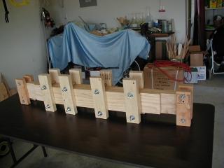
Started making the upper supports for the thrust duct.
3/13/2002
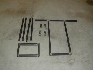
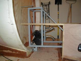
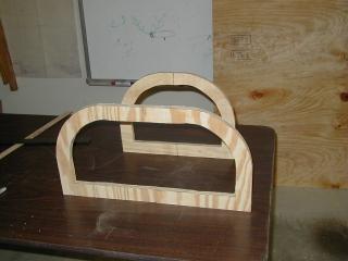
The top picture is of the supports for the thrust duct. They are
getting a layer of fiberglass. Next is the frame that will go over
the top of the prop shaft and bearings. It will have 1/8" plywood
as a skin. Then the last picture is the trust duct supports being
fiberglassed to the duct.
4/7/2002
Mounted the thrust engine to the engine frame and ran the exhaust with
flexible pipe. A local custom muffler shop wanted $80 to bend the 2
pipes. $80 will buy a lot of flexible pipe. Once the engine was in the
stand, the stand with the engine were finally added to the craft.
4/14/2002
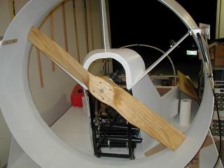
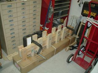
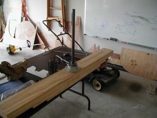
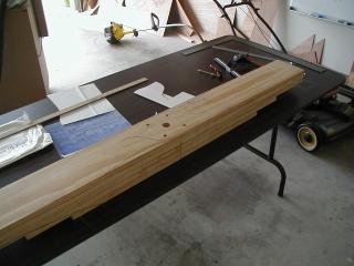
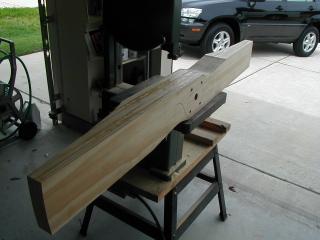
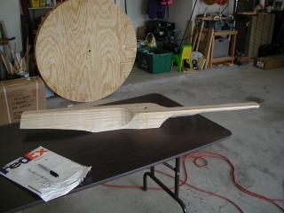
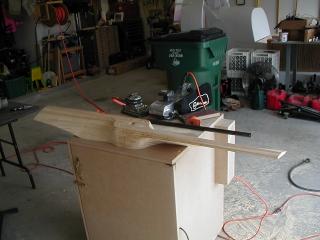
Cut and shaped the thrust prop today. Here are some pictures during the
process. The boards were glued together a couple of nights ago.
Here are some of my secrets for creating a prop. Drill all of the holes in the prop before cutting it. It is easier to clamp a square block of wood to the drill press. Cut as much wood away with the saw, it will make the sanding go quicker. When using a bandsaw to cut the shape, make several light passes to get close to the lines.
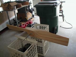
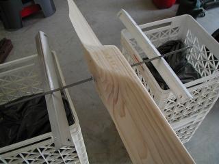
There are a couple of pictures of my prop balancer. It is a 5/16" steel rod with tapered wooden bushings to center the rod in the prop shaft hole. The whole thing rides on a pair of extruded angle aluminum.
4/18/2002 & 4/21/2002
The prop is glassed and balanced. Went for a test fit in the duct.
I spun the prop by hand and it moves a lot of air! It should be
interesting to see how well the prop is matched to the engine. Now
that the prop shaft is in the correct spot, the upper drive pulley was
set in place to measure the belt length. The belt is on order and
should be here in a couple of days.
Painted the prop. Now it has to wait 48 hours before painting the red tips.