10/28/2003
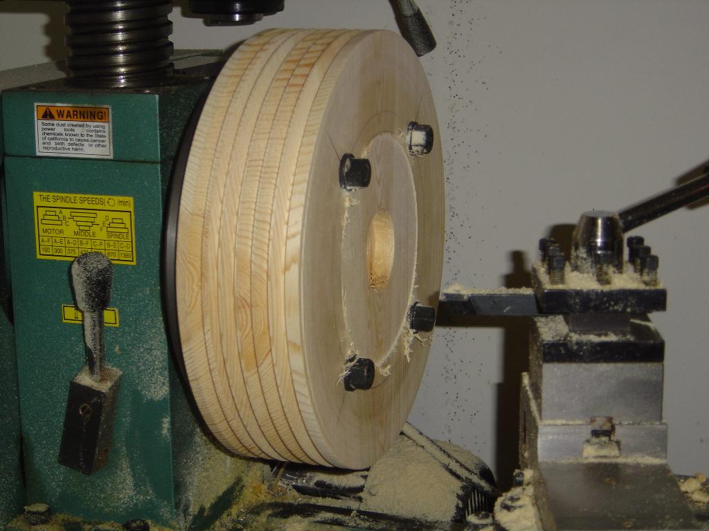
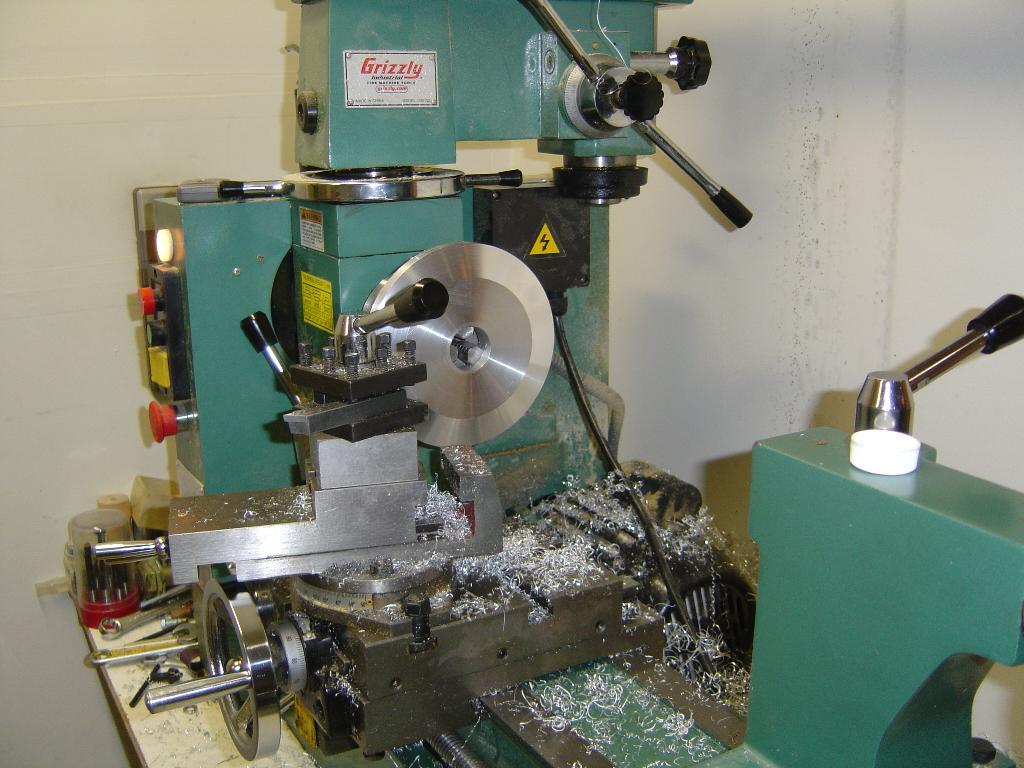
I have started working on the smaller piece parts before tackling the
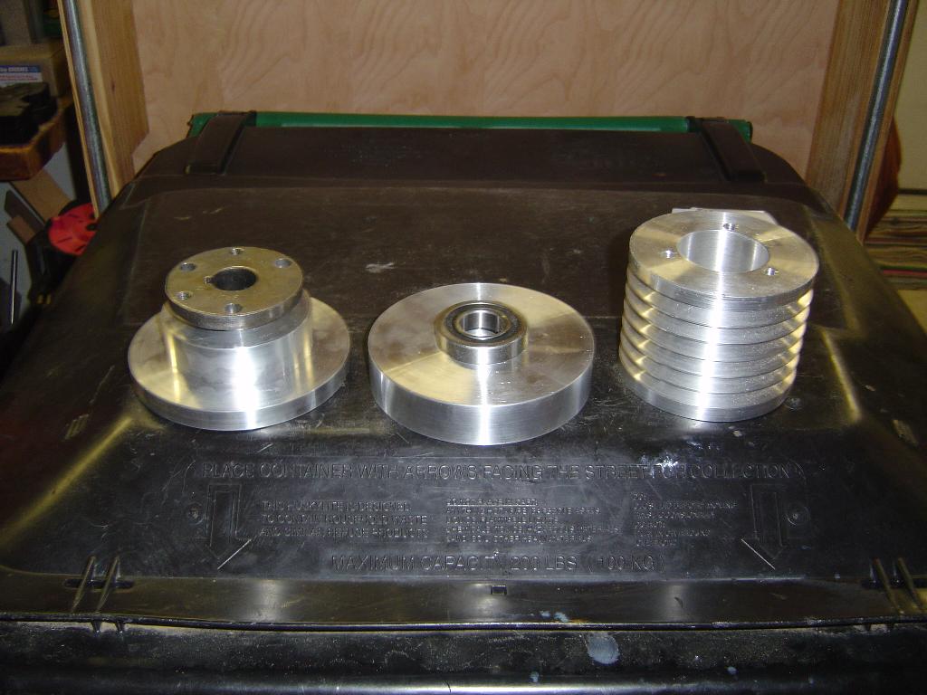
hull. Here are some pictures of the 6 groove pulleys that will be used
to drive the 60" thrust prop. This was my first time making pulleys
with my lathe. I made a practice pulley out of wood to learn the
process. The wooden pulley in the picture is not the practice pulley,
it is the real upper pulley. It is getting very close to the limit
of my lathe.
Click on an image on the right to see a bigger image.
11/24/2003
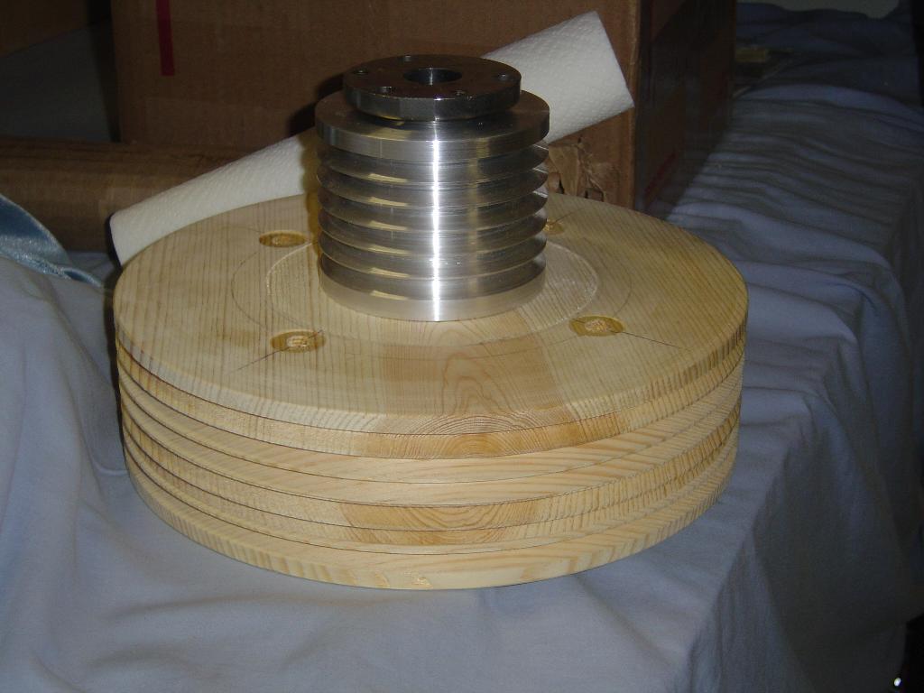
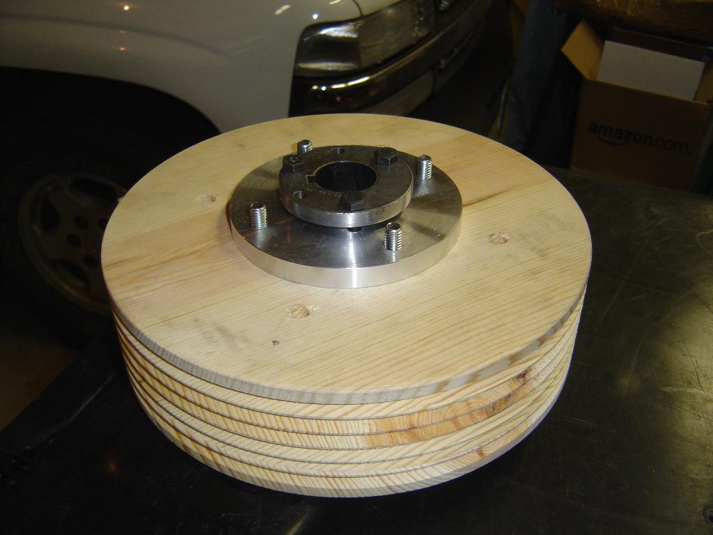
The normal method for mounting the pulley to the shaft is by using a
split taper bushing. Normally the pulley has the mating taper cut into
the wood and the bushing is drawn into the wood. Some people have
compressed the wood to the point where the bushing would not tighten.
I created an inset flange from aluminum that will fit between the bushing
and the pulley.
1/7/2004
With the new year comes more construction. I finished other items that
required attention before construction on the 15S could really begin.
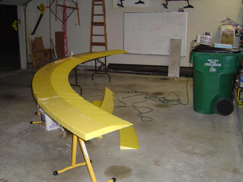
My dad came for a visit so I made him help with the foam for the
thrust duct. We used a hotwire to cut the foam and the picture shows
the sections of foam being glued together. After the picture was taken,
the foam received the outside layer of fiberglass and it is ready to be
wrapped around the duct. The duct forms have been made. Once the
weather warms, I can make the plywood cylinder that wraps around the
duct forms. Then the foam wraps around the plywood cylinder.
1/12/2004
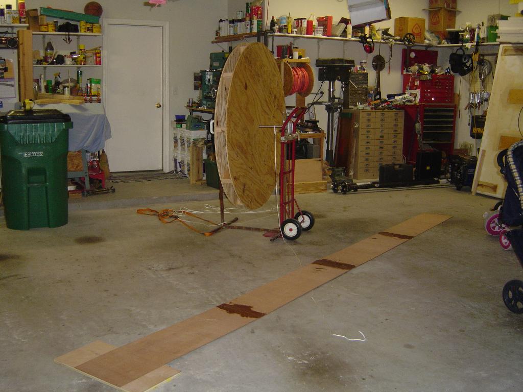
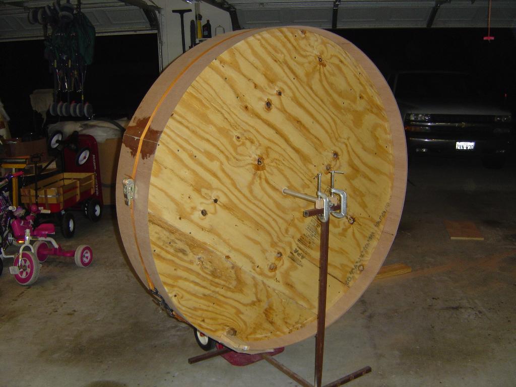
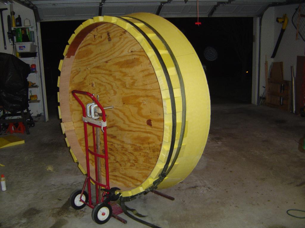
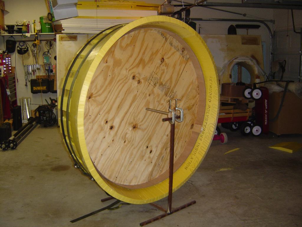
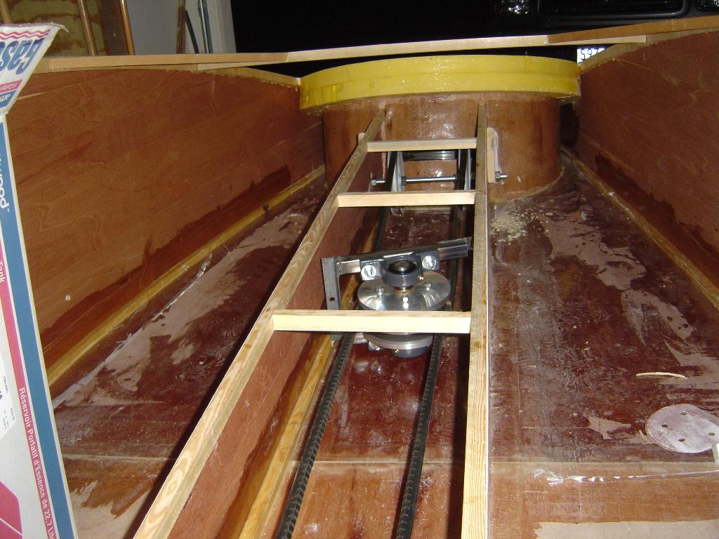
Worked on the thrust duct tonight. The 1/8" plywood liner that forms
the inside of the thrust duct was fitted around the 60" discs. The
liner is held in place with a ratchet strap while the remaining seam
is fiberglassed. Once that seam sets up, the duct will be ready for
the foam.
1/14/2004
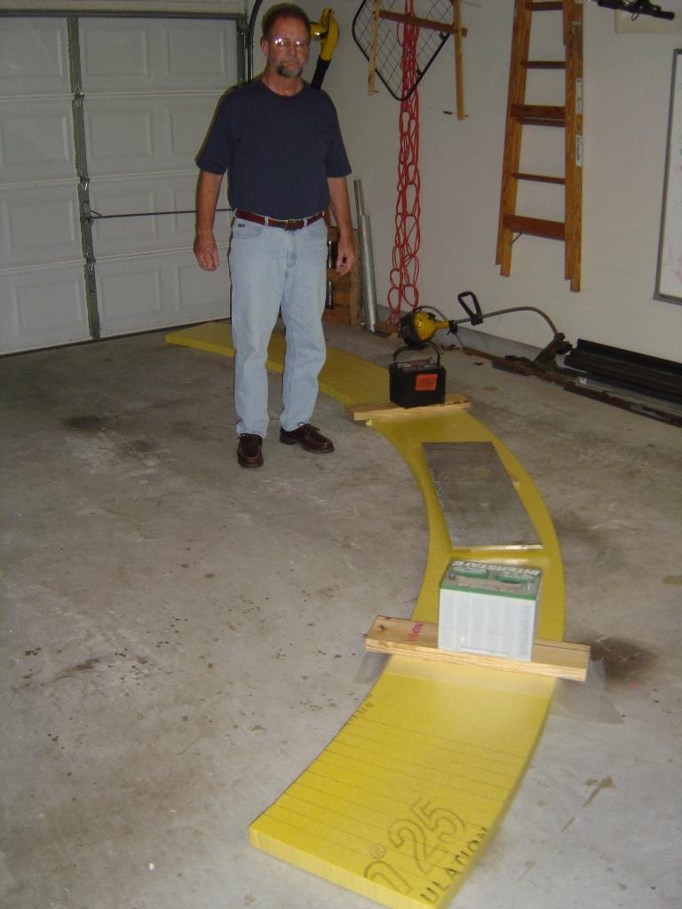
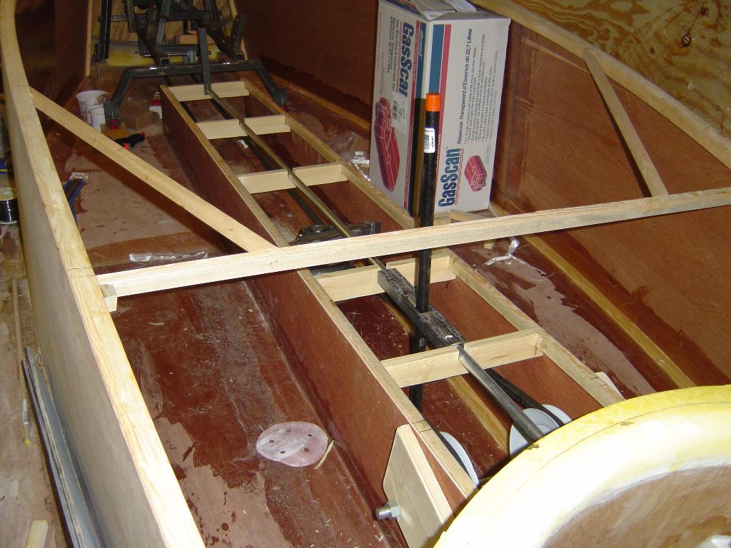
The foam for the thrust duct has had the taper cut and then the foam
was wrapped around the plywood liner.
1/20/2004
Started turning the pieces for the variable ratio pulley called a
variator. The variator is used in flight to change the ratio of the
of the drive to the lift fan. This allows more control over the amount
of power sent to the lift fan.
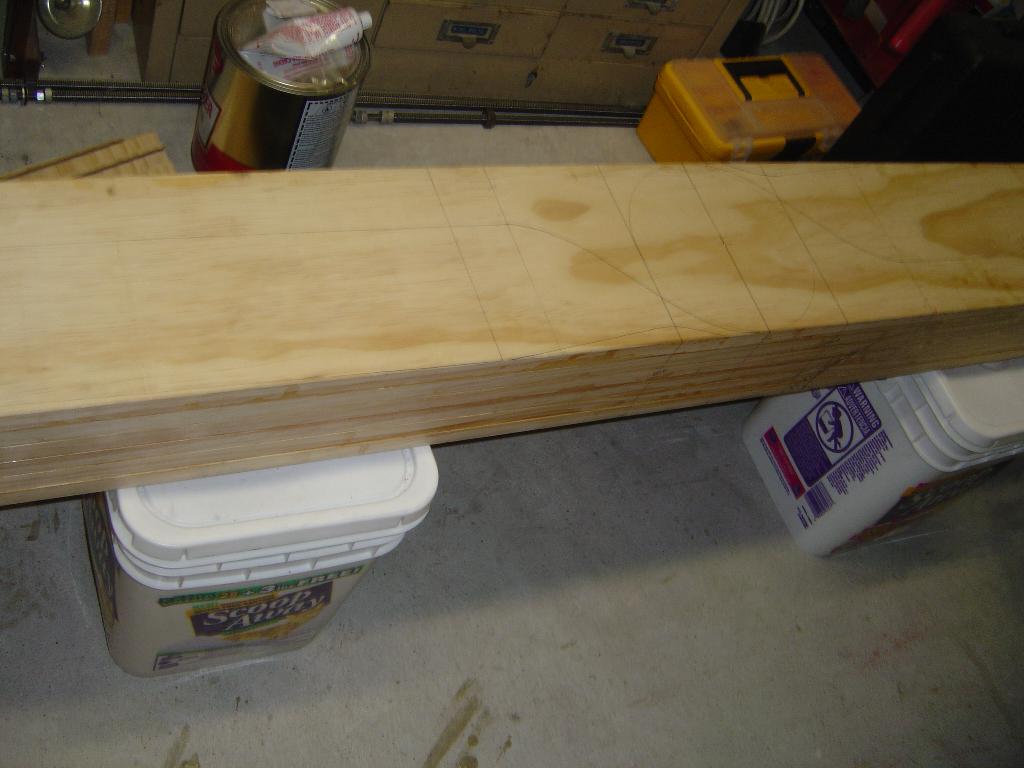
2/21/2004
The blank for the thrust prop is glued together and marked for cutting.
I just need some quality time with the chainsaw and it will look more
like a prop.
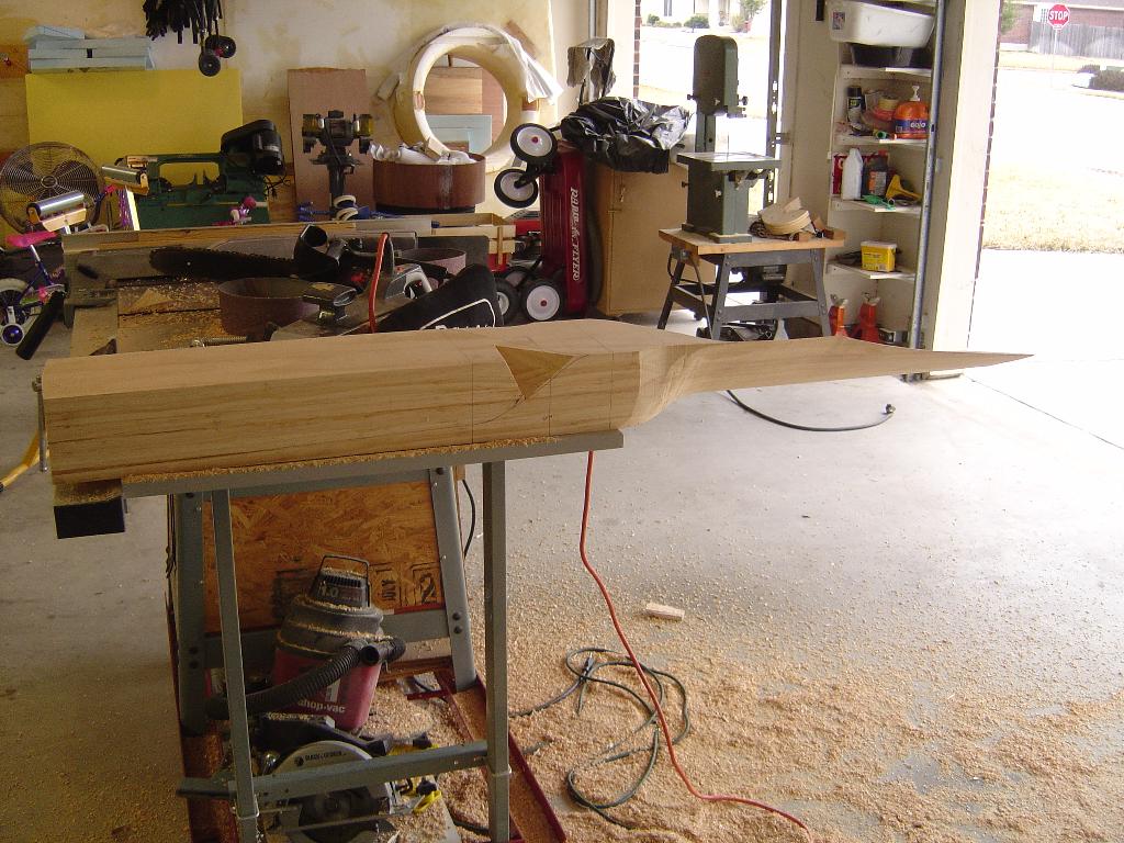
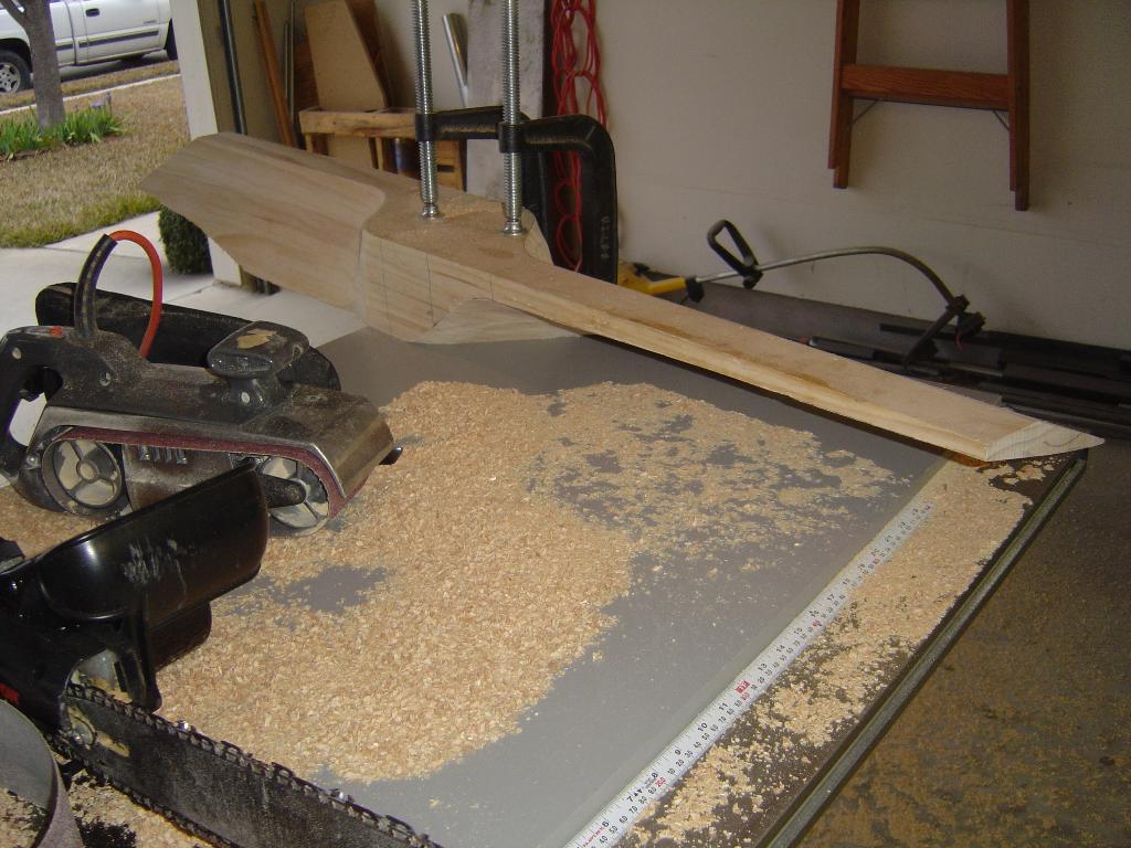
2/22/2004
I was able to start cutting the thrust prop. The first picture shows
the prop with one of the blades cut. Notice the mound of sawdust.
most of the wood removed is turned into sawdust. The second picture
show the prop with both blades cut to the lines. The prop still needs
to have the airfoil shape cut, but the bulk of the cutting is complete.
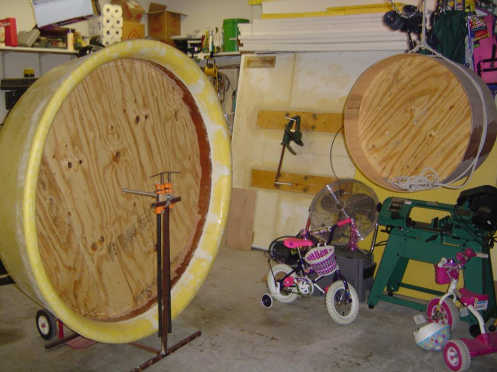
2/23/2004
The thrust duct is completely glassed. All it needs is a hovercraft to
mount to the bottom of it. The top picture shows the thrust duct and
the lift duct. The hull is on its side leaning against the wall in the
background. It should be laying on the ground soon.
The second picture is the 6 groove upper pulley and its hub. The pulley received a coat of epoxy to keep the water away from the wood.
2/27/2004
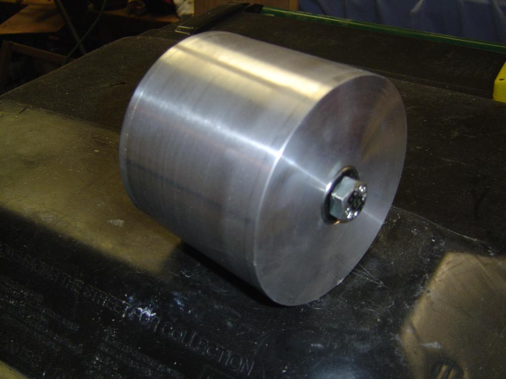
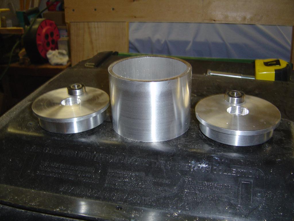
Worked on machining the backside idler for the thrust belt. The idler
is 4 1/2" in diameter and 4" long. It is constructed from 5 parts. 2
bearings, 2 end caps, and the center sleave.
4/27/2004
The thrust belt came in and it is actually the correct length. The
belt is a 6 groove, common back belt. The guy that I bought it from
said that he can get belts up to 40 grooves with a common back. The
6 groove belt looked impressive until he said that.
5/5/2004
The lift belts came in and they are the correct length too! I had to
make a new swing arm for the lift belt idlers in order for the belt
to line up. I also started work on the rudder/trim wing controls. I
am going to use a torque tube down the center of the of the seat tunnel.
In front of the engine, the torque tube will attach to a set of cables
running to the rudders. This will be a simple system that won't have
cables running in the cockpit.
6/8/2004
I had been toying with the idea of making a disconnect for the thrust
prop. This would be used to disengage the thrust prop in order to back
the craft off of the trailer. I had planned to build this after the
craft is flying. But I decided to work on it now before everything is
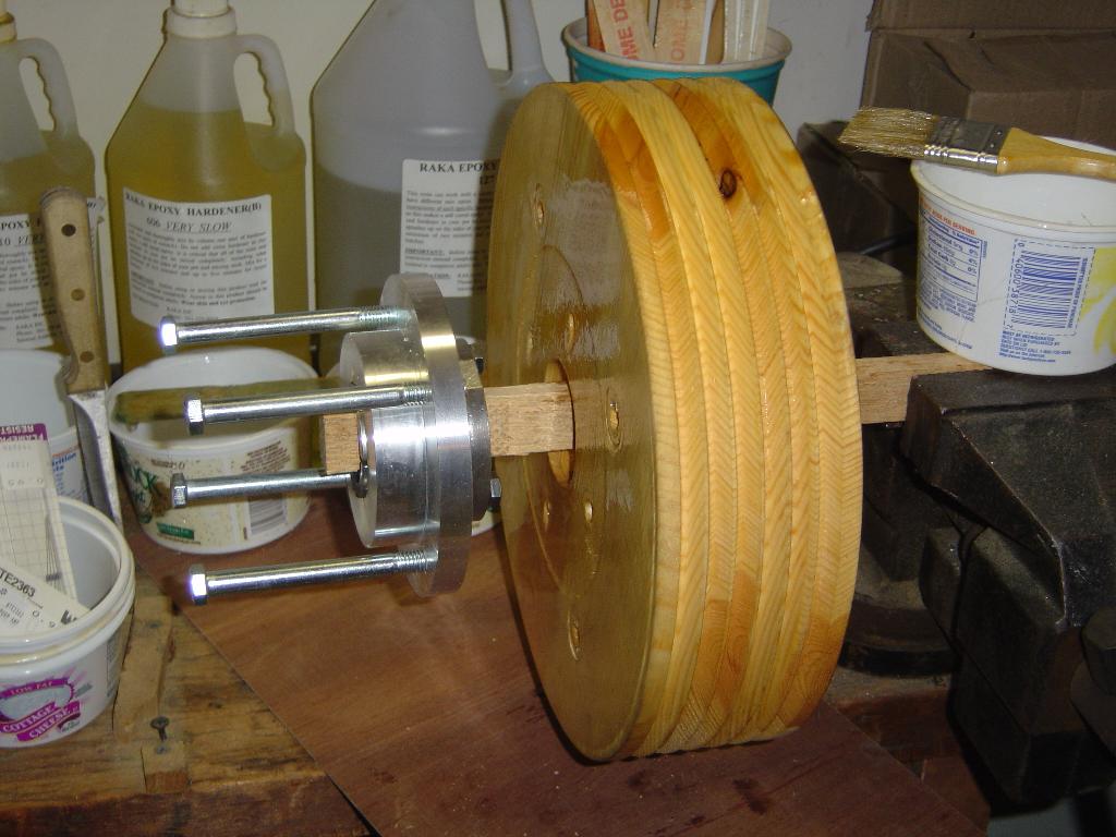
put together. Normally the drive pulley is mounted directly to the
output shaft of the engine. I will put a set of bearings between the
output shaft and the drive pulley. This will allow the shaft to turn
while the pulley is stationary. Since the pulley is no longer directly
mounted to the output shaft, there has to be a way to get the power from
the engine to the pulley. There will be 4 removable pins that will
transfer power from a flange that is mounted on the output shaft to the
pulley. The 4 pins will be spring loaded. No tools will be needed to
disengage the prop. The engine will have to be stopped, the 4 pins
will be pulled back from the pulley to disengage the prop.
6/14/2004
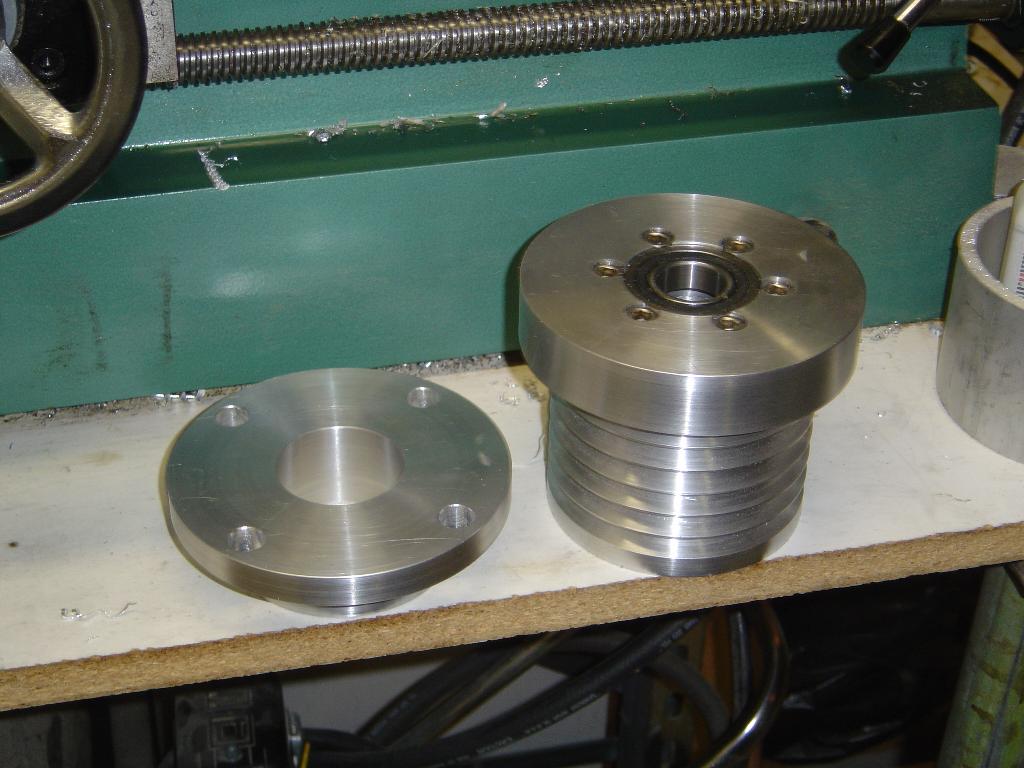
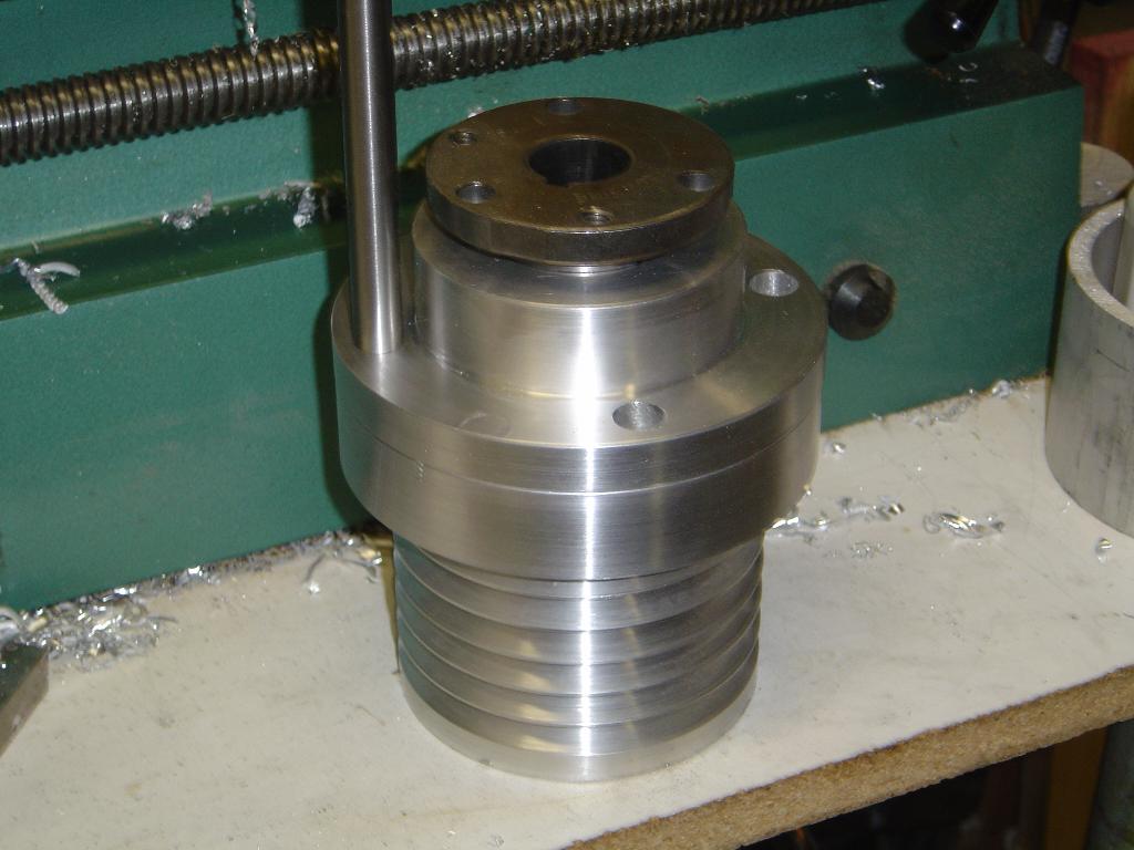
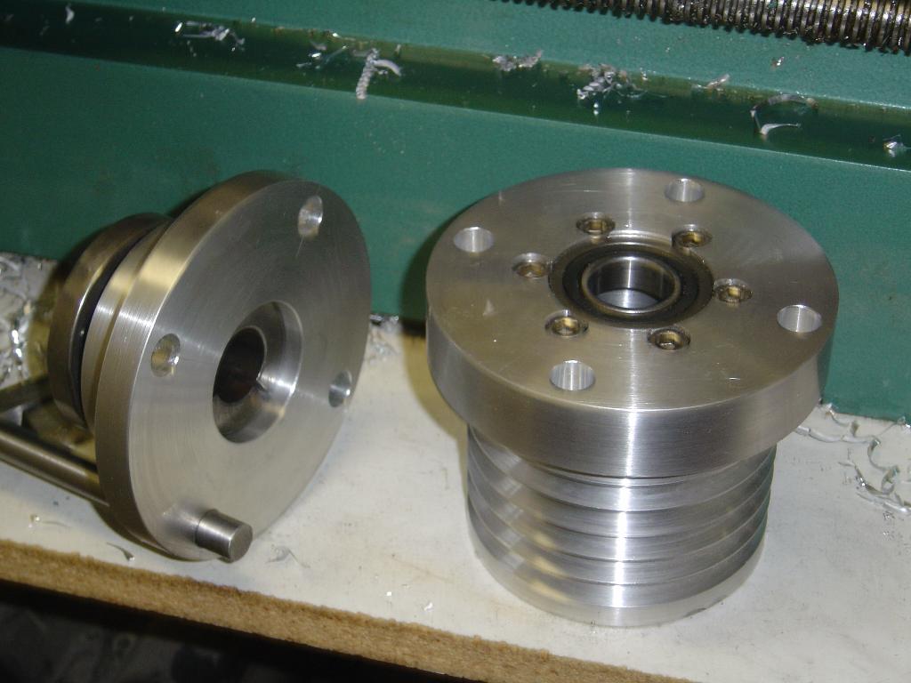
More work on the thrust disconnect. The first picture shows the 2
flanges. The one on the left will be fixed to the output shaft from
the engine. The one on the right is connected to the thrust pulley and
will have a set of bearings which allow the lower thrust pulley to not
spin while the engine is running. The second picture shows the 2
halves put together with a test piece of steel that will become one of
the 4 pins.
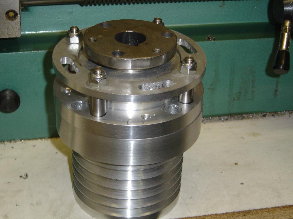
6/16/2004
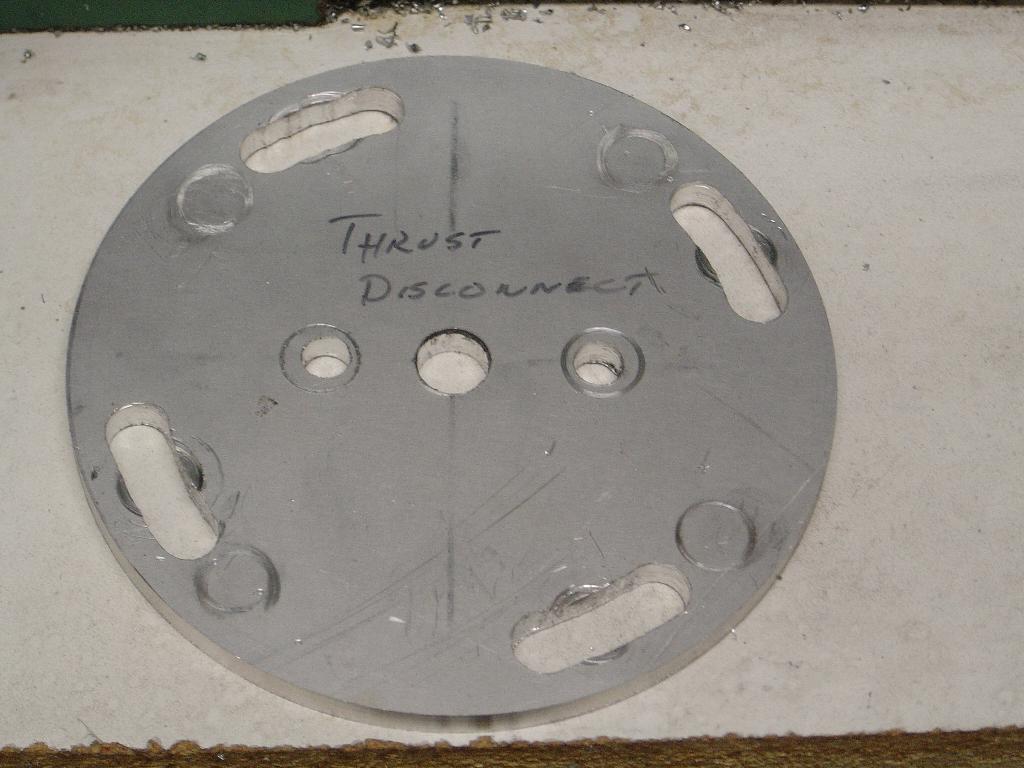
More work on the pin plate for the thrust disconnect. The top picture
shows the slots that were cut using a rotary table on the mill. These
are the slots that will allow the 4 pins to be rotated out of the
holes to their idle position. The next picture shows the center of the
pin plate being opened. The last picture shows the pin plate in place
on the fixed flange. The 4 bolts are there to check movement. They
will be replaced with longer bolts and springs to keep the pin plate
pressed against the fixed flange.
6/23/2004
Almost done working on the thrust disconnect. The first picture is one
of the four 1/2" diameter stainless steel pins that are used to connect
the two flanges. The pins have a 5/16" diameter stud. I used my lathe
to turn the threads on the studs. This is the first time that I cut
threads on the lathe. That is the best tool.
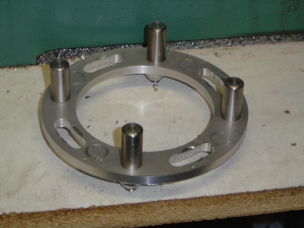
The next picture shows the 4 pins in the pin plate.
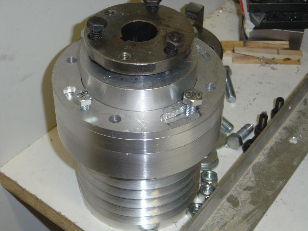
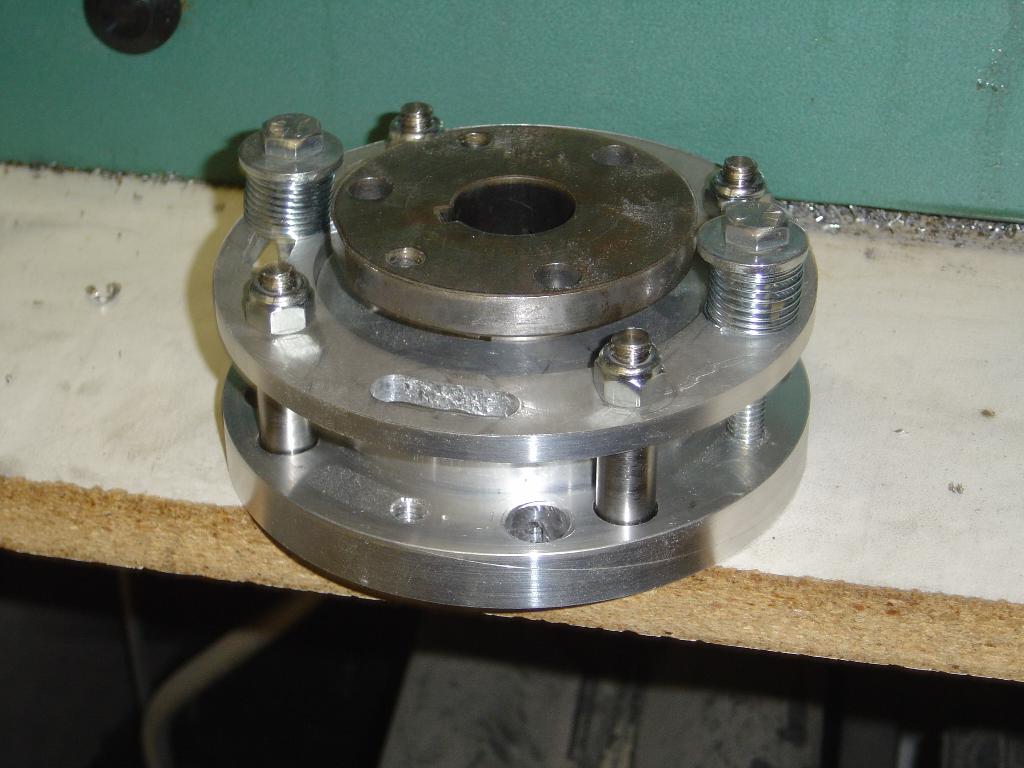
The third picture shows the pin plate connecting the 2 flanges. This is the engaged position where power will be transferred to the pulley.
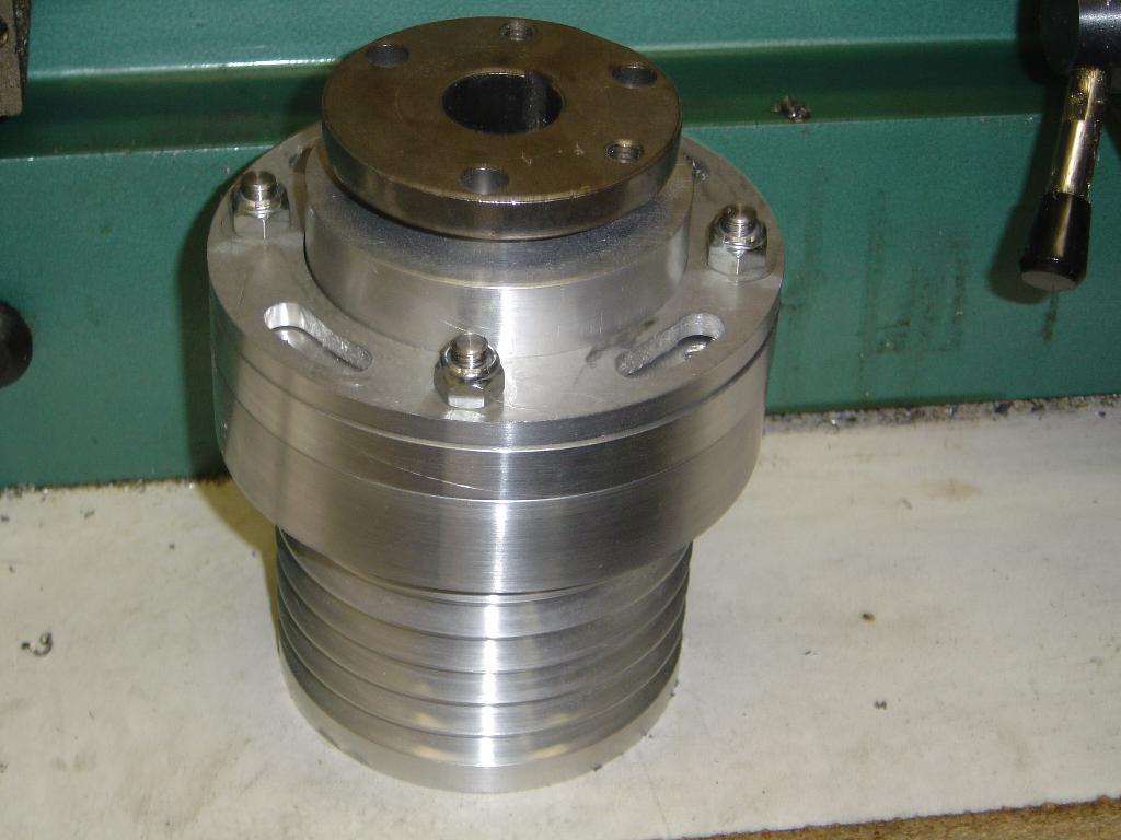
The forth picture shows the pin plate in the disengaged position. With the pins in this position, no power will be delivered to the pulley. This will allow the engine to run without the prop turning.
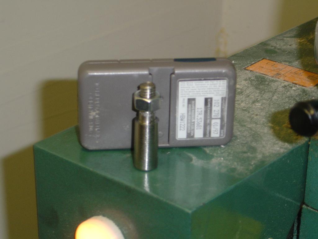
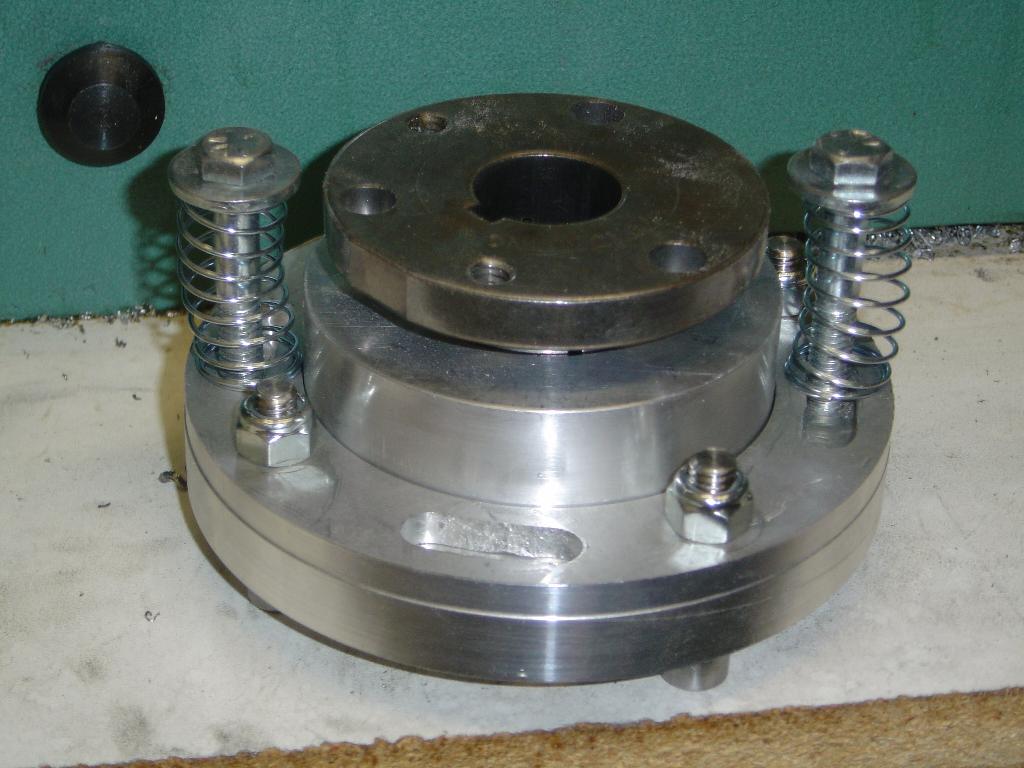
The fifth and sixth pictures show the springs that will hold the pins from popping out of thier holes. Only 2 springs are shown, there will be 4 springs used.
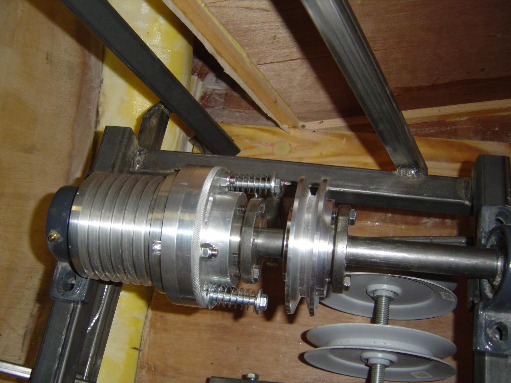
7/6/2004
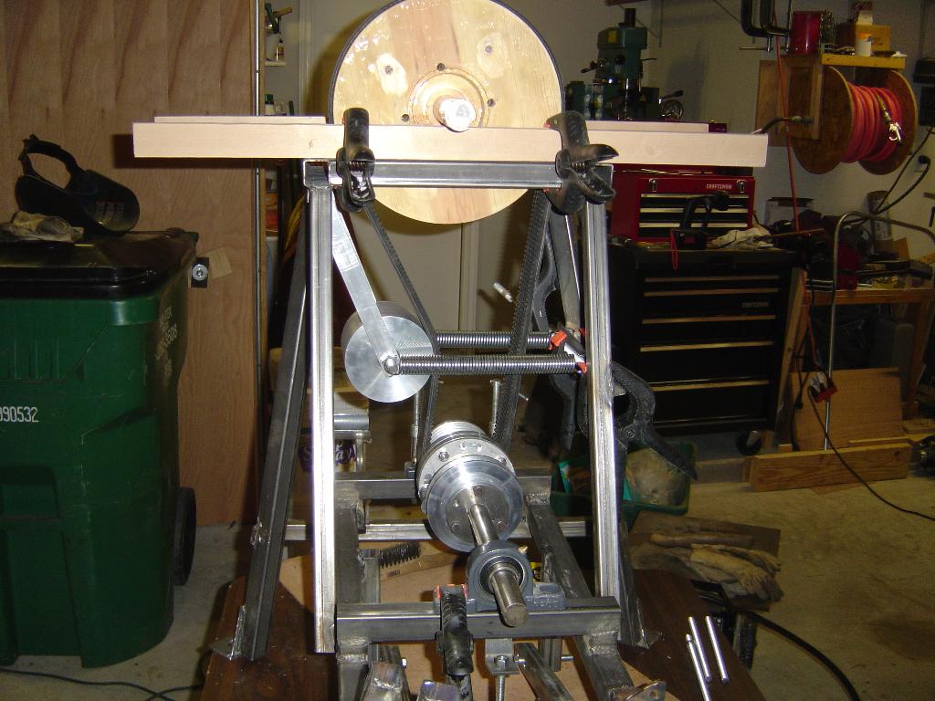
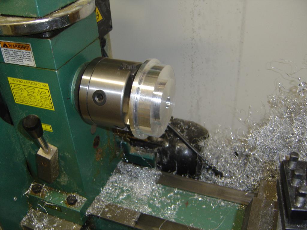
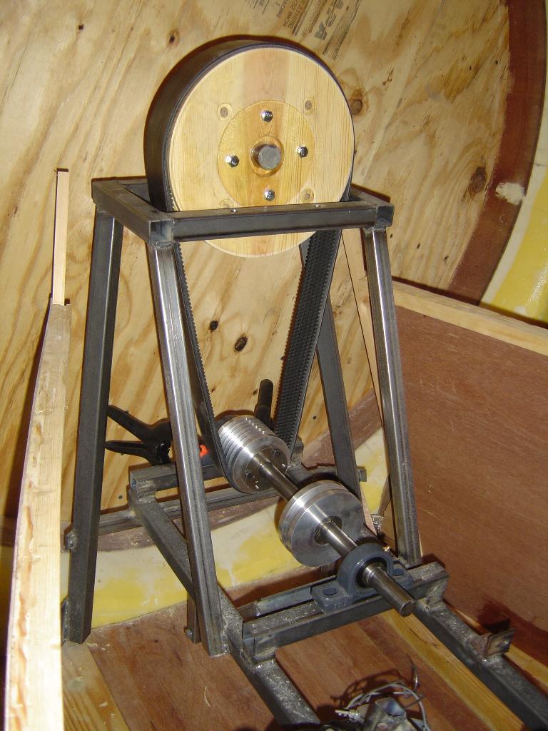
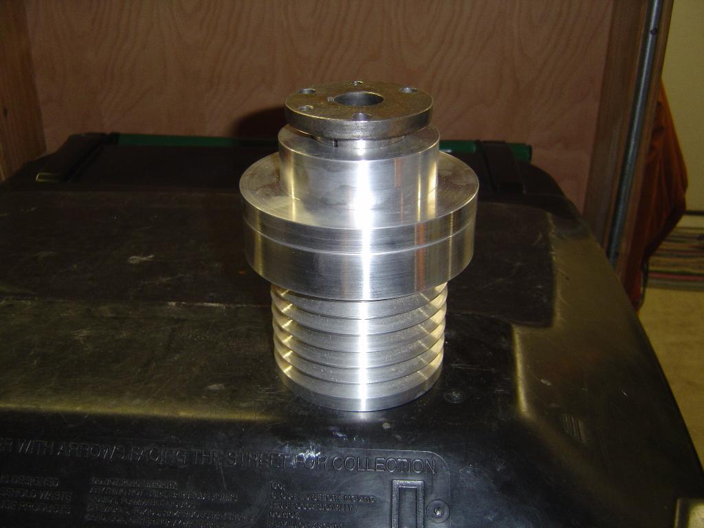
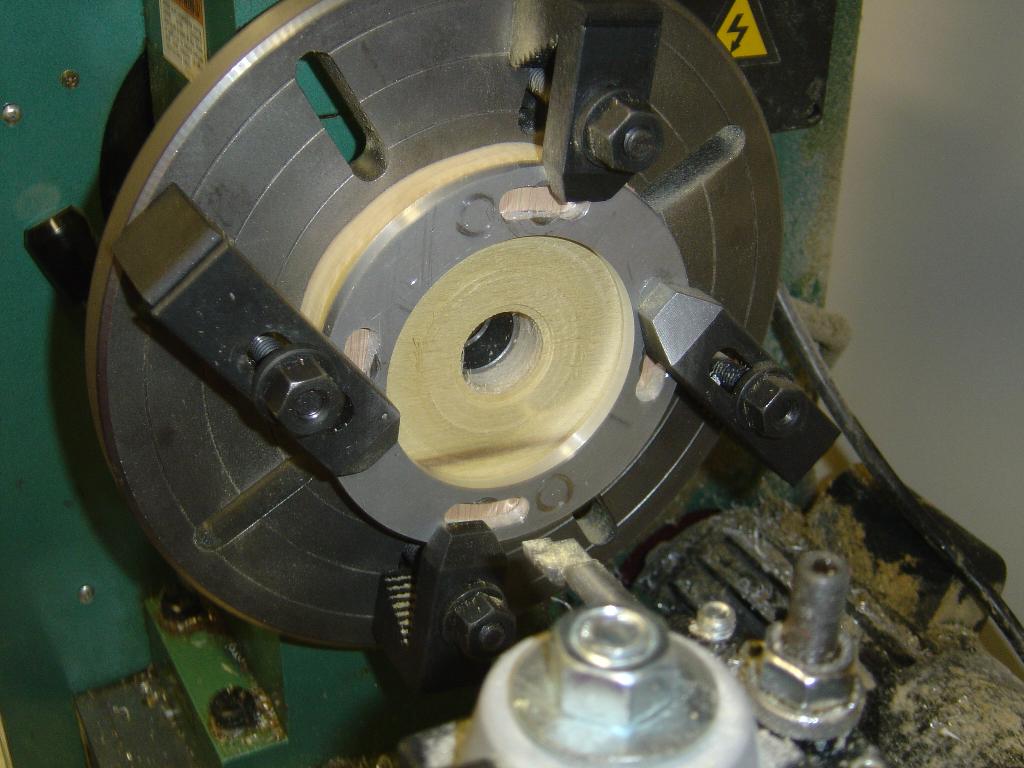
I have been drilling and tapping all of the holes in the components
for the drive. The picture shows the thrust disconnect placed on the
output shaft from the engine. I was worried that I made the thrust
disconnect too long and the drive pulley for the lift fan would not be
able to line up. But the alignment looks good.
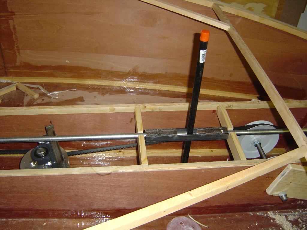
7/8/2004
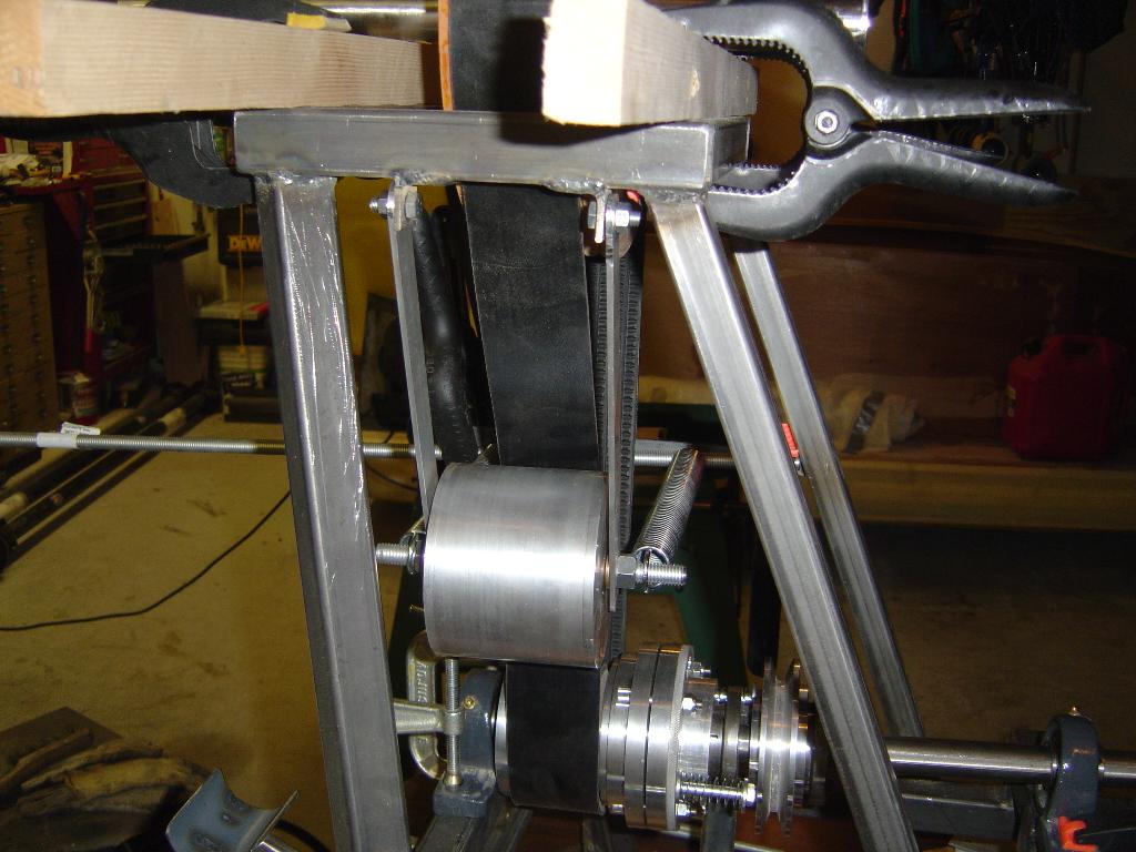
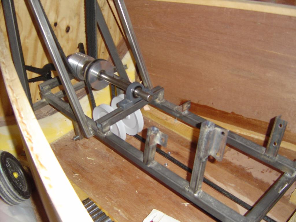
Started mounting the backside idler for the thrust belt. The idler is
mounted on a swing arm and tensioned with a pair of springs.