1/27/2004
Finished working on the variator. Now I just need a hovercraft to
go along with it.
Click on an image on the right to see a bigger image.
2/21/2004
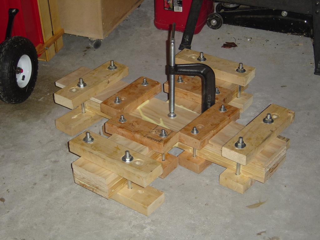
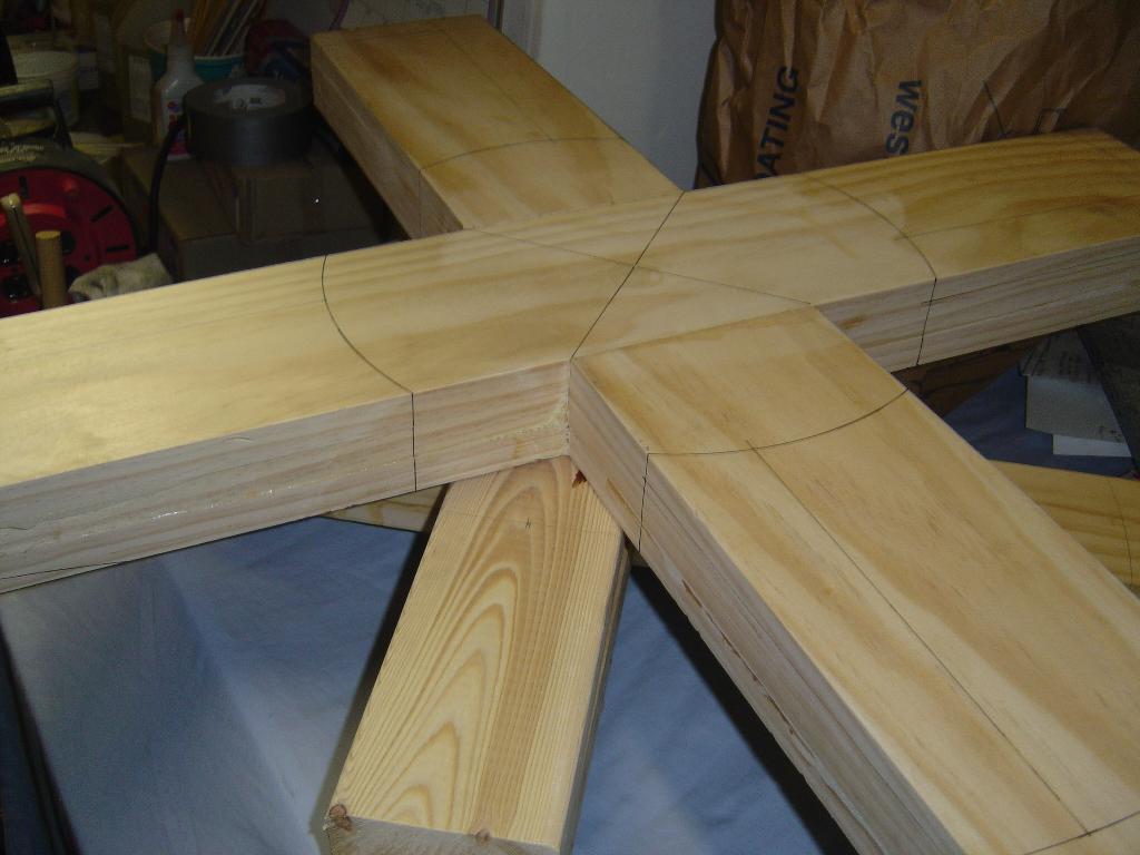
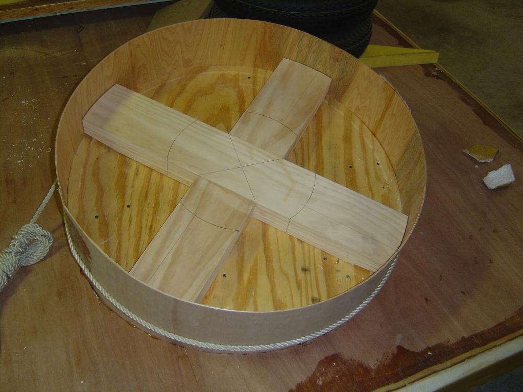
The blank for the lift fan is glued together and ready to be cut. The
second picture shows the lift fan blank sitting on top of the fan blank
for my daughter's 6F. It needs to be cut also.
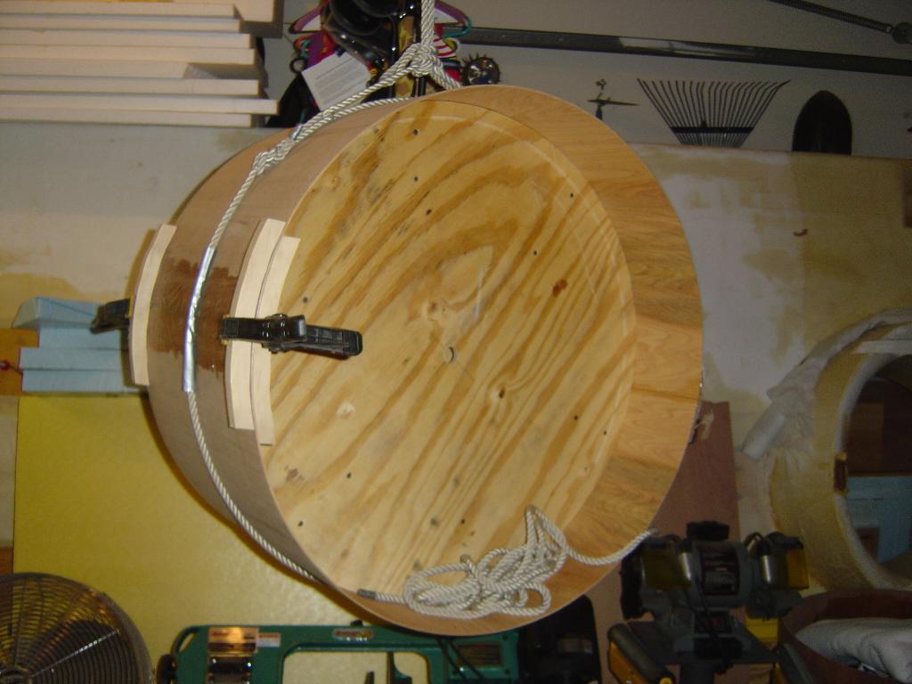
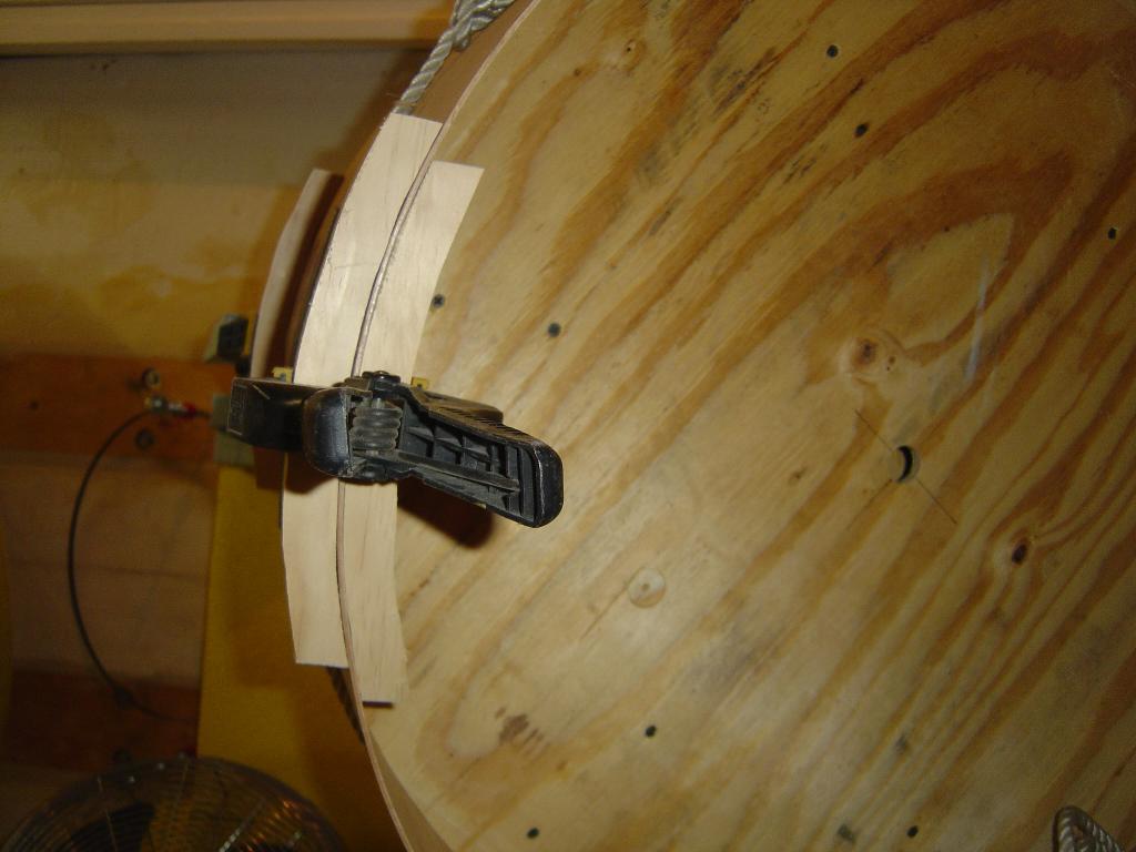
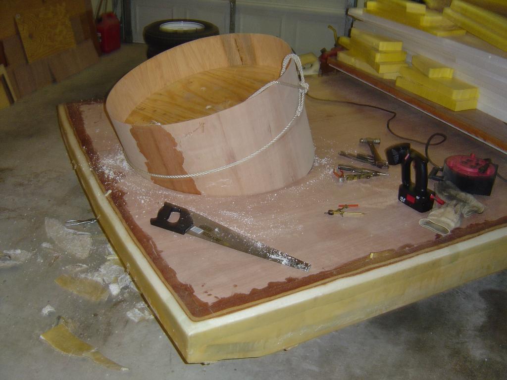
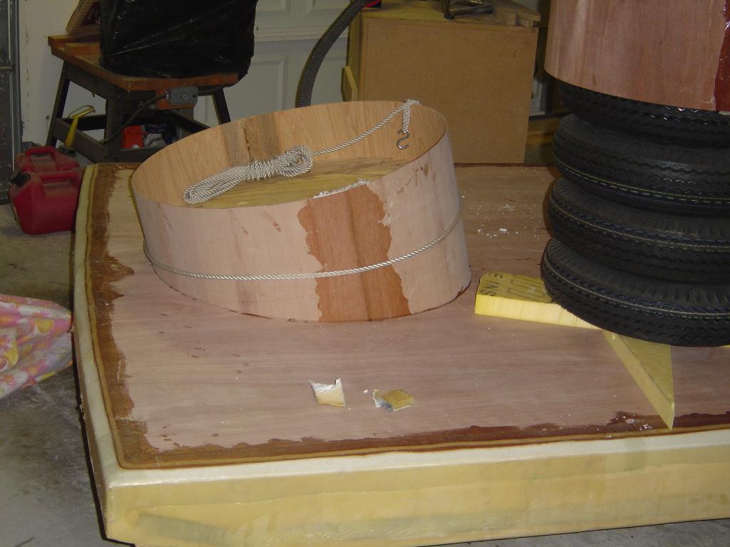
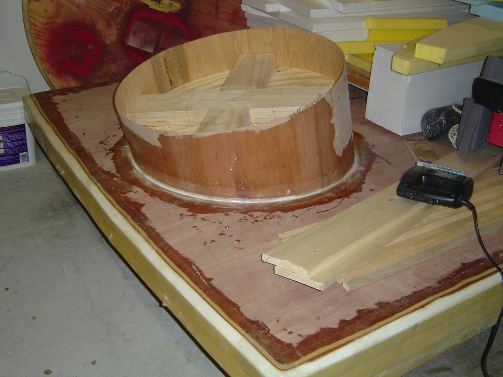
The plywood liner for the lift fan duct has been wrapped around the form. This is the seventh duct that I have made and it has gone together easier than any of the others. The plywood wrapped perfectly around the form without a lot of persuasion.
The last picture shows the clamp that I made to maintain the shape out to the end of the plywood.
Click on an image on the right to see a bigger image.
3/4/2004
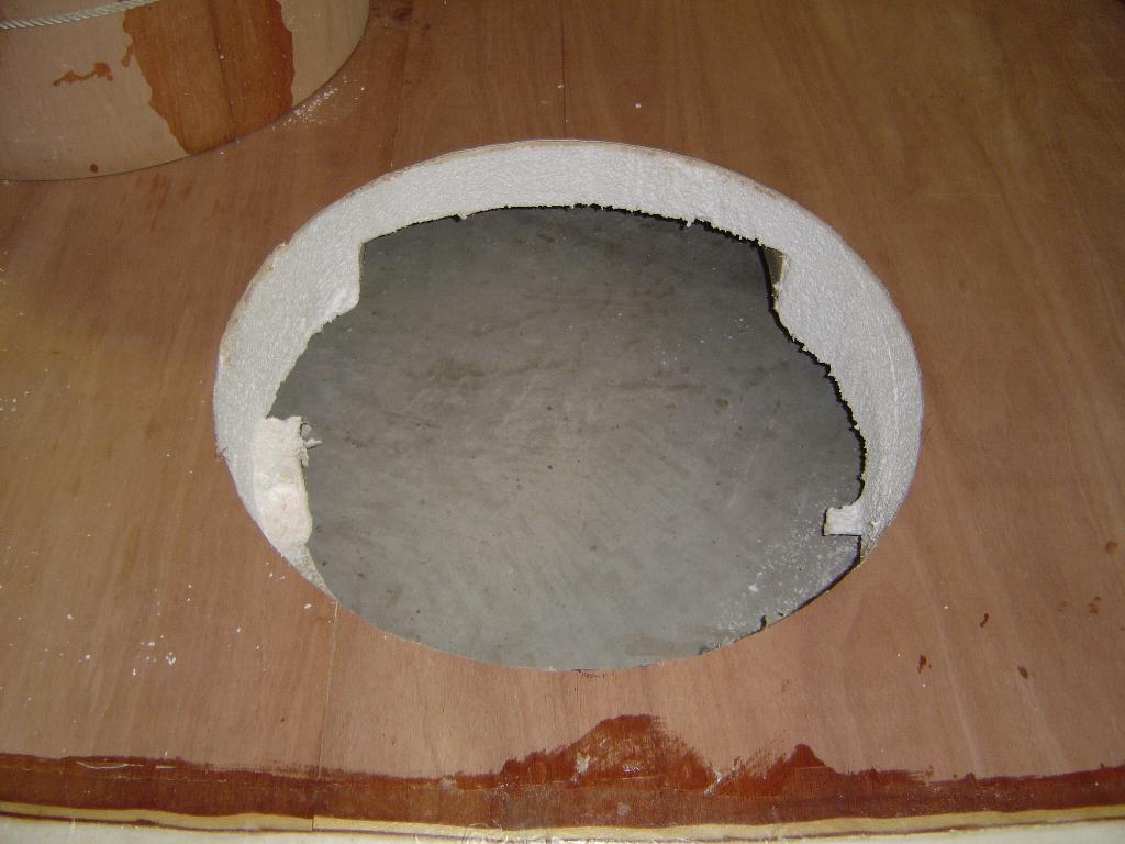
Worked on the hole for the lift duct. Howard had a duct in the hull for
a 26" fan. Since I will be using a 30" fan, the 26" duct had to be removed.
Howard did a great job on the 26" duct. I know this because it was such
a pain to remove. The carbon fiber and Kevalr is a pain to remove. I
don't want to do that again.

3/8/2004
Glued the lift duct in the hull. Tomorrow the craft will be flipped
upside down and the bottom of the duct will be finished.
3/15/2004.
Fiberglassed the lift duct to the to of the hull. I hate fiberglass!
4/12/2004
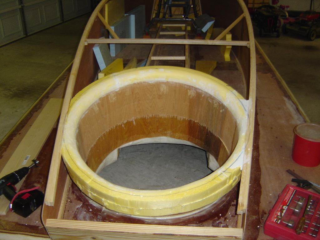
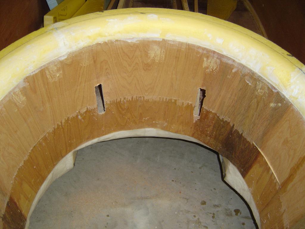
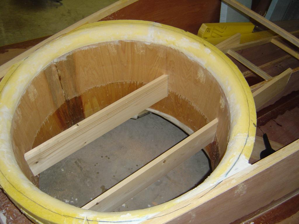
Rounded off the foam inlet ring on the top of the lift duct. The
outside of the lift duct has been covered with Kevlar just in case the
lift fan tries to enter the cockpit. Next, the lift duct form was
removed and the two supports for the lift fan were glued in place.
These boards go through the lift duct in the front and the back.
4/25/2004
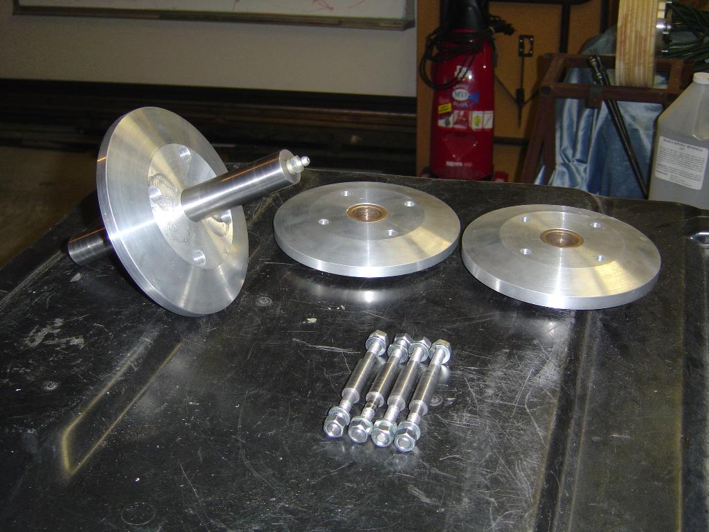
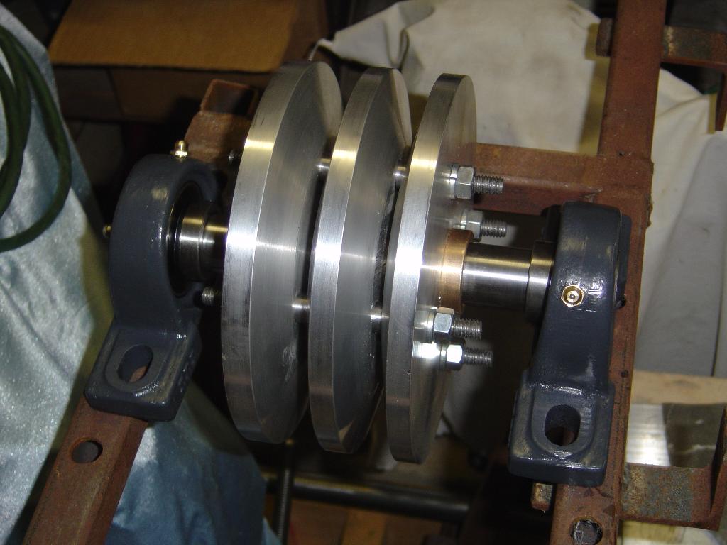
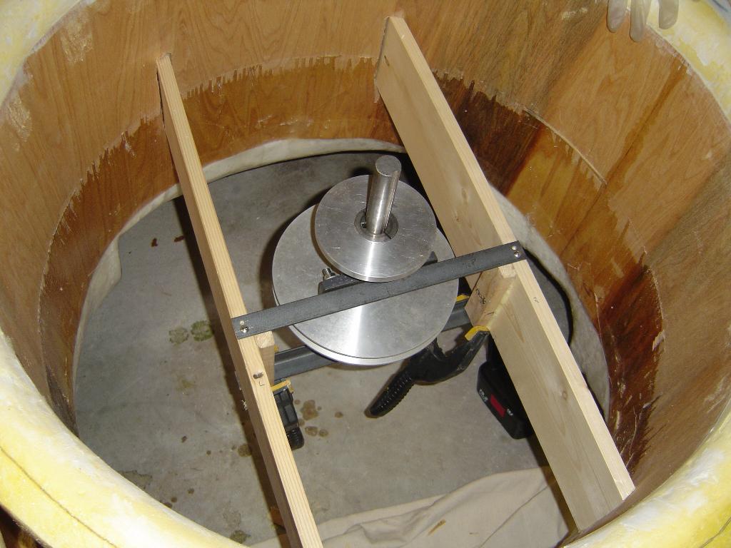
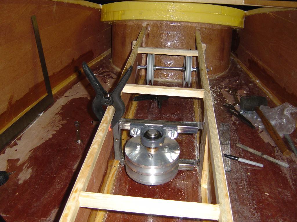
The top picture shows the lift fan drive assembly. A single V-belt
will come from the engine and drive the aluminum pulley.
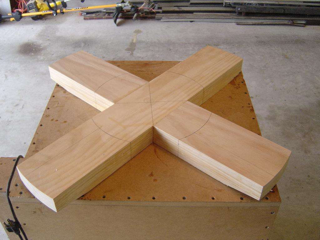
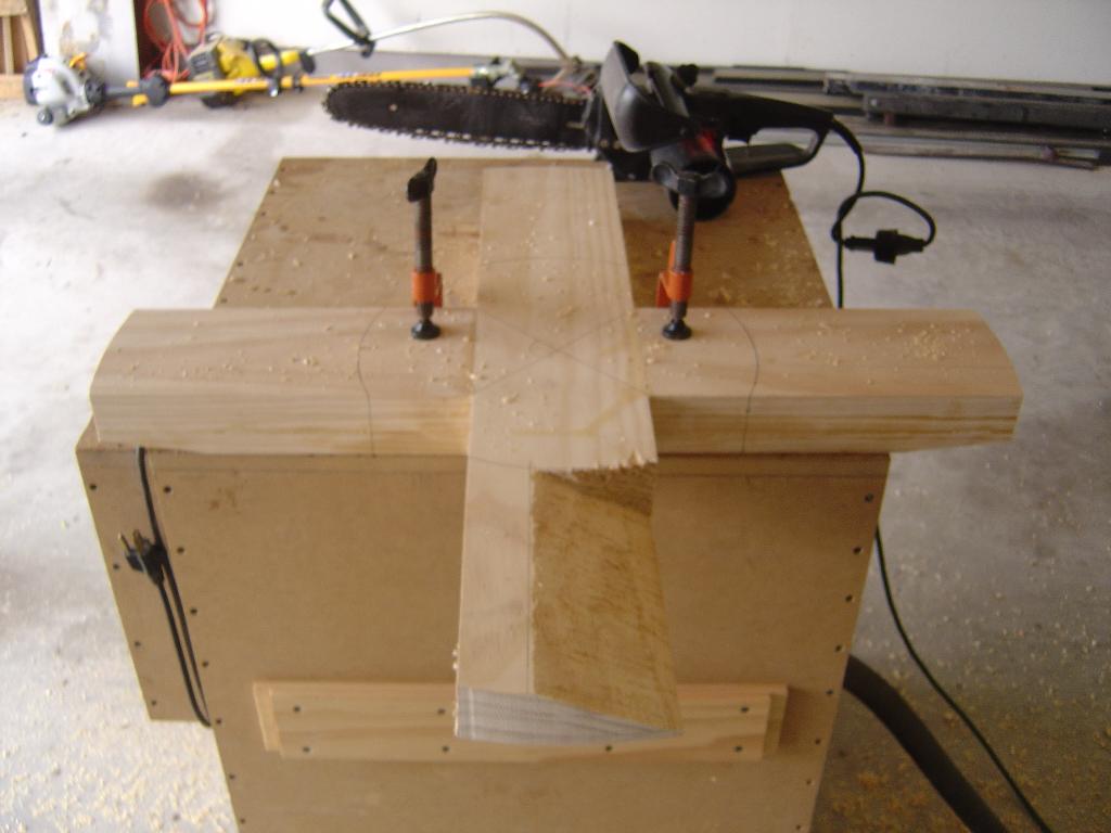
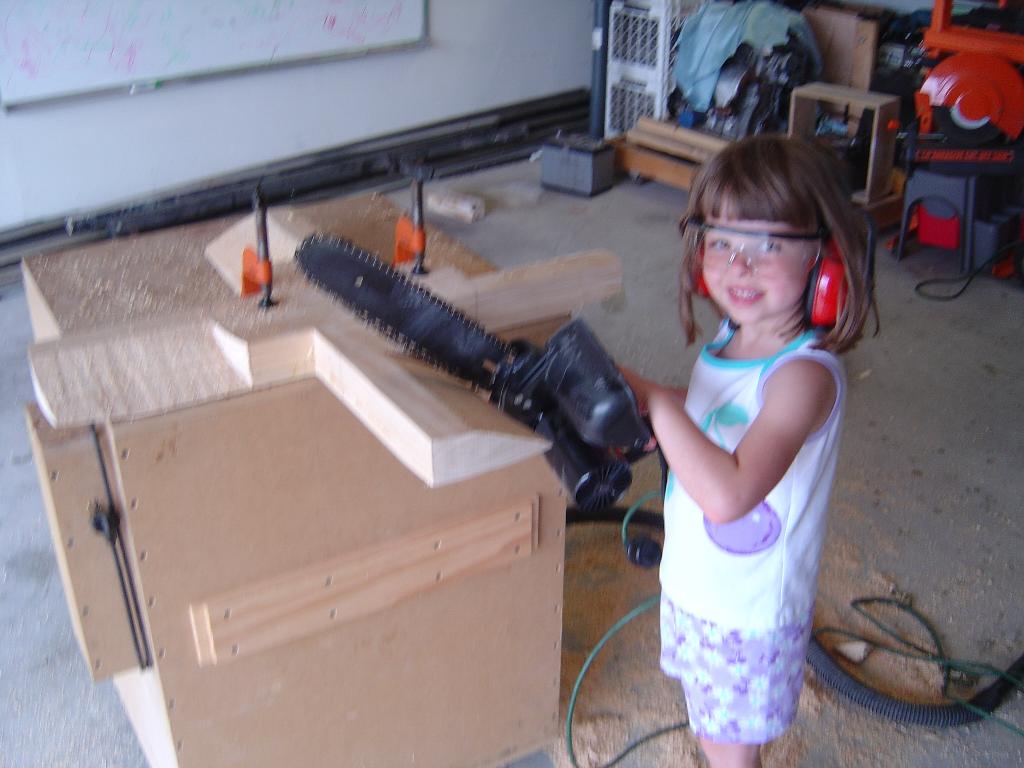
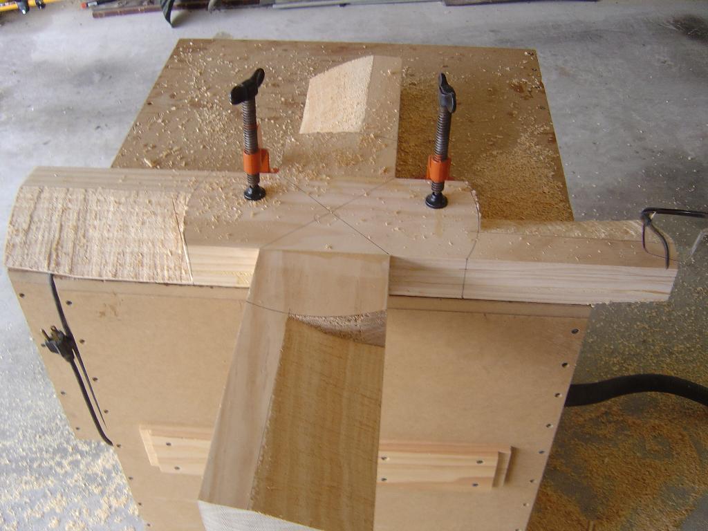
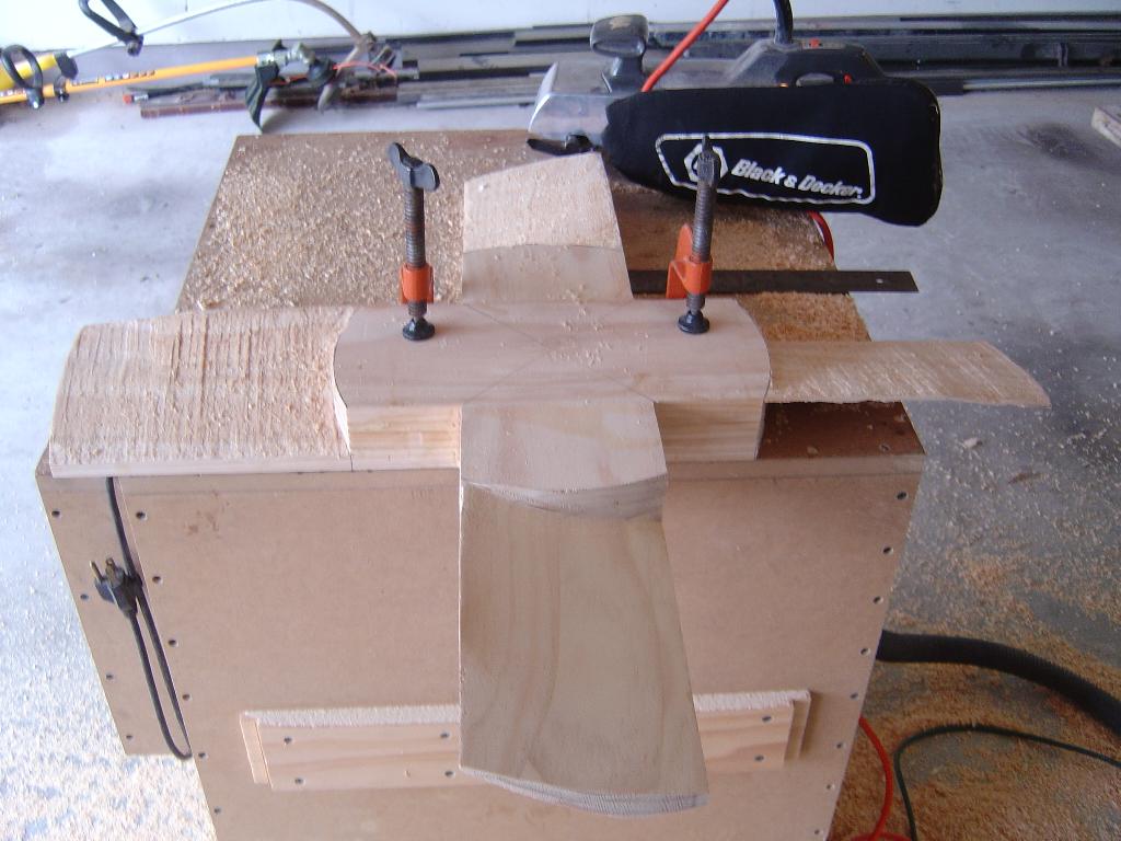
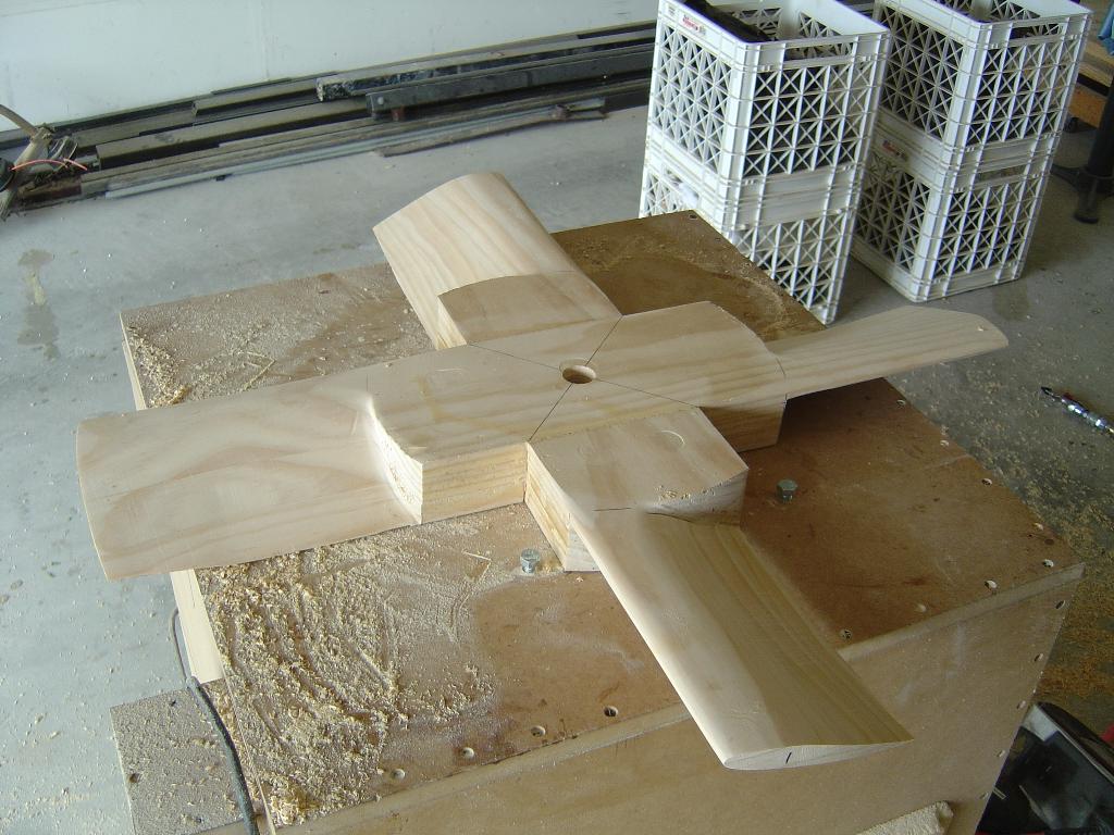
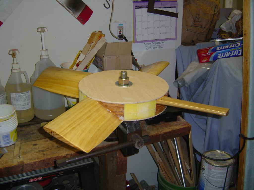
The next set of pictures show the creation of the lift fan. It took 4 hours to cut, shape, and balance it. I started with a blank that had previously been glued together. Then the fan is rough cut with the chainsaw. A band saw also works well for props, but does not cut all of the way to the hub on fans. After the prop is rough cut, the belt sander is used to bring the blades to the lines. This will leave the fan with a squared-off air foil. The sander is used to smooth the blades into a nice air foil shape.
4/29/2004
The variator was set in place in the seat tunnel. By placing it in
the seat tunnel, the variator should stay out of the evironment. Now
that the variator is in place, I was able to measure for the lift belts.
5/5/2004
The plywood centers for the lift fan have been cut and trued on the lathe.
The blades are ready for the final sand and balance after the centers
have been epoxied.
5/26/04
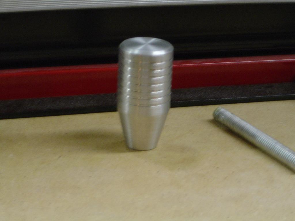
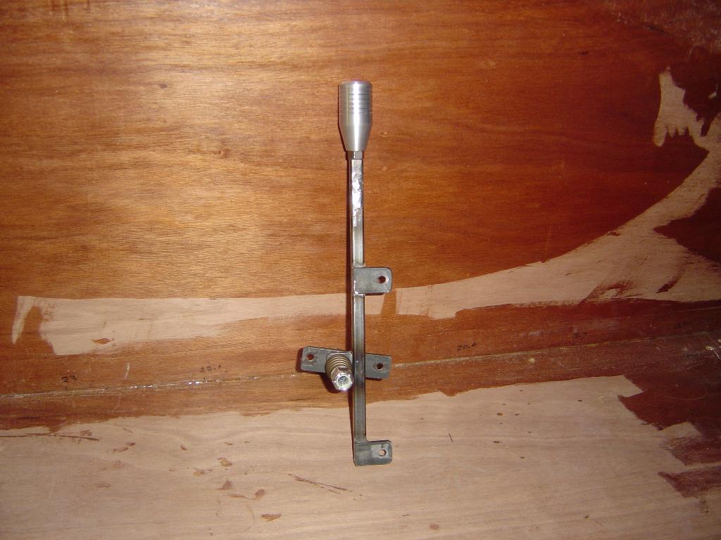
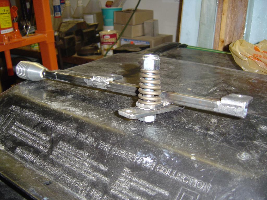
Made the variator control lever. I put the lathe to work making the
handle from some scrap aluminum. The spring will provide pressure for
the friction lock on the lever. If it moves, the tension on the spring
can be tightend to increase the holding power.